ABB in Metals
ABB in Metals. Industrial IT solutions for Processing Lines. Topics. Drives System Automation System (Level 1) Manufacturing Execution System (Level 2). Topics. Drives System Automation System (Level 1) Manufacturing Execution System (Level 2). Applications Hot Rolling Mills
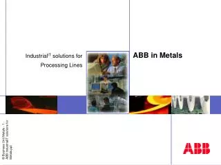

ABB in Metals
E N D
Presentation Transcript
ABB in Metals IndustrialIT solutions for Processing Lines
Topics • Drives System • Automation System (Level 1) • Manufacturing Execution System (Level 2)
Topics • Drives System • Automation System (Level 1) • Manufacturing Execution System (Level 2)
Applications Hot Rolling Mills Cold Rolling Mills Profile Rolling Mills Processing Lines High performance Drives Fast torque step rise time High dynamic speed accuracy Excellent process controllability Wide range low voltage AC Drives From 5 ... 5140 kVA, 380 ... 690 V Modular configuration Stand-alone Multidrive (Common DC bus configuration) Wide range DC Drives From 22 to 5150 A DC, 380 to 1000 V AC Modern rebuilt kit for revamps Drives System for all metals applications
DTC has 25 microsecond control loop Traditional PWM: • Control in short steps to avoid overshooting • Control loop time 1-3 ms because of modulator Frequency reference V/F ratio Modu-lator V AC f • Vector control: • Tachometer feedback required • Control loop time 1-3 ms because of modulator Speed control Torque control Modu-lator V AC f T • DTC principle: • Torque controlled by a single step • No risk of overshoot with fast 25 s control loop Speed control Torque control AC • Backlash appears in gearboxes and couplings. In backlash range motor may accelerate leading to backlash impact. Fast DTC control limits impact. • Mechanical resonances often appear due to elasticy of shafts and inertias of motor, gearbox and driven machine. Fast DTC attenuates the resonances.
SwitchingLogic Torque and Flux Comparator Torque Reference Controller Torque Reference = Speed control PID ~ REF Speed Reference Torque and Flux Switchpositions Voltage Current Motor Model 3~ DTC CORE Calculated Speed Direct Torque Control • Advanced drives control
1,00 New Current level Current 0,50 Time 0,00 Torque New Torque level DTC Vector DTC, Direct Torque Control, fast and gentle Servo performance without high switching frequency (no useless switching) Always to the correct value by single switching Frequent torque monitoring prevents overshooting Torque is always correct.
Direct Torque Control increases drive performance • Advanced drives control Fast Torque Step Rise Time High Dynamic Speed Accuracy Torque Torque Open Loop DTC Speed Closed Loop Flux vector Speed error Open loop DTC 0.4 %sec Open loop flux vector 3.0 %sec Closed loop flux vector 0.4 %sec Open loop DTC < 5 msec Open loop flux vector > 100 msec Closed loop flux vector 10 to 20 msec
DTC, Less stress to mechanics • Backlash appears in gearboxes and couplings. In backlash range motor may accelerate leading to backlash impact. Fast DTC control limits impact. • Mechanical resonances often appear due to elasticity of shafts and inertias of motor, gearbox and driven machine. Fast DTC attenuates the resonances.
DriveBus To overriding control Process Section Line Entry Section Drives system reduces energy consumption • Multidrive configuration • Common DC-Bus possible • Energy consumption is reduced • Compensating other loads is possible • Dimensioning of incoming sections and transformers or supply can be smaller • means lower investment
Drive Section(s) Supply Section Control Section(s) DSU TSU ACU ICU Common DC Bus DriveBus To overriding control AMC AMC AMC AMC Diode or Thyristor Supply Unit ~ Inverter Inverter Inverter Inverter ~ PC Tools: Drive Windows AC Hardware with Modular Construction
Intelligent Control Panel • For global use - display with ten languages • Easy monitoring - four-line display • Supports maintenance - fault memory • Removable panel • Quick and easy commissioning with the parameter copying feature • Selection and parameterization of application macros
Commissioning and Maintenance Drives Window Tool • Displaying system configuration • Auto tuning functions • Monitoring actual signal values • Fast and accurate measurements with data logger • Viewing and changing parameters • Logging faults • Logging events • Local control of drives • Controlling and debugging applications • Backup and restore
Topics • Drives System • Automation System (Level 1) • Manufacturing Execution System (Level 2)
Drive Drive Drive Drive Drive Drive ... ... ... ... ... ... Integrated control system OIT & MES Server Control rooms (entry, proc., exit) Computer room Hydraulic room Switch-House Event / Alarm Hardcopy ... MMS, TCP/IP DriveBus • Reference Generation & Seq. • Auxiliary Logic & Sequencing • Reference Generation & Seq. • Auxiliary Logic & Sequencing • Reference Generation & Seq. • Auxiliary Logic & Sequencing • Strip tracking, Presetting & Recording Entry Process Exit Other functions
Availability and integration of information • OperatorIT • One single interface for all applications • Data integration • From production data to alarm & events • Operation efficiency
Simulation Production order Control Functional Description Production schedule Product specification Operator Graphics Operator interaction Cost ofoperation Stock report Production report Quality report Production report Quality report Profiledata Maintenance Record OperateIT, Keeping IT together... Metals Customer need a way to keep together all different aspects of plant and process entities (objects)
You can always find out in what graphics an object is represented Right mouse click to show the context menu and look in the Reference Item Makes it possible to navigate for examples from the Alarm List to the graphic Trend to the graphic Graphic to graphic ... Automatically configured User Interface - Automatic from Object to display
State of the art process graphics Use the latest technology for creating graphics Openness Make use of the extensive amount of ActiveX control available on the market Include any photos, scanned images, or live images of your choice Process Graphics - General
Special SW & HW for the needs of the rolling mill process • Rolling Mill Control • Ultra fast communication between controller • Precision time marking for ms timing between duty cycles • Fast connection to pulse generator and absolute encoder • Fast Drives interface • Special program building block for efficient engineering on the ControlIT platform
ControlIT AC800 Hardware • Modular and flexible concept, DIN-rail mounted • Scalable hardware - various CPU variants • Built in RS232, ModuleBus and redundant Ethernet • Optional communication modules • Hot swap I/O modules • Local and remote I/O options • Very low power consumption • Industry quality hardware with excellent EMC and MTBF properties
IBM PowerPC 750FX 500 MHz 128 Mbyte RAM 16 Mbyte Flash Memory Cycle times: Control Builder Layer 1ms C-Code Layer 1ms ... 100µs VHDL Layer 100µs ... 1µs ControlIT AC 800PEC Hardware
Up to 12 communication modules on Any-IO CEX Bus 2nd Any-IO can be used for e.g. Profibus Up to 6 Profibus communication Interfaces in CEX Bus Optical Module: One link for Module bus for S800 or Drive communication Other links can be used for special AC800PEC I/O or fast CPU point to point communication Up to 7 S800 I/O clusters on the optical ModuleBus Up to 12 S800 I/O modules per cluster 7 x 12 = 84 I/O modules Remote I/O via Profibus DP up to 32 Stations on a Profibus Segment up to 24 I/O Modules per Station ControlIT AC 800PEC Hardware • Any-IO, PEC 800-AIO-CEX • 2 x Any-IO • CPU module, PEC 800-CPU • 2 x Ethernet 100MBnd • 1 x Serial RS232 • Optical Module, PEC 800-OM • 2 x Optical Module with 3 or 6 optical links per module Stackable up to 3 modules
ControlIT, Choose Your Language • Standard Easy to use IEC 61131-3 • All five languages supported • Instruction List (IL) • Ladder Diagram (LD) • Function Block Diagram (FBD) • Structured Text (ST) • Sequential Function Chart (SFC) • Additionally • Control Module Diagram
Fast, incremental, bump less online changes Powerful Test & Simulation Off-line program check and simulation Single stepping On-line facilities Easy made user defined function blocks for unmatched flexibility Saves Engineering work On-line help and manuals Control Builder M Make your first application in 30 minutes!
HMI • Line Supervision • Setpoint Management Overriding Controls • Reference Generation • Auto Slow Down • Emergency • Weak Point tracking Drives Controls • Looper Control • Roll Control • Bridle Control • Coiler Control • Roll Control • Coiler Control • Roll Control SW configuration for Processing Lines
Start conditions Threading Operation Process Entry Exit Process Entry Exit User Interface - Structure for Processing Lines Main Menu Start up Operation Mode Presetting Menu Process Data Start Conditions Strip Tracking System-, Alarm-, Event- & Status-Lists Automatic Operations Presettingper Coil- Entry- Process- Exit Start Conditions Sequences Start up Conditions Mimics Coil PreparationEntry, Process, ExitCoil Transport Entry Coil Transport Exit (Status List) Power SupplyHydraulicsGear Lubrication
Metals Solutions based on OperateIT Process Data Display
Metals Solutions based on OperateIT Sequencing
Metals Solutions based on OperateIT Presetting & Reporting
Metals Solutions based on OperateIT Status List
Electrical Equipment for Processing Line Continuous Processing requires: But We Are not only a products supplier, We know more about metals application…. • For Mechnical equipment • Welding at Entry and cutoff at exit • Entry and Exit Looper for coil exchange • For Electrical Equipment • The strip speed must be constant and continuously adjustable within wide limits • Acceleration / deceleration should be performed quickly and steadily without producing any impact forces • The drives must always be well synchronized or operate in groups in relative synchronism • With defined tension distribution, which can be adjusted at certain groups in the strip processing line, the strip has to be moved over long distances and many rolls symmetrically to the axis of the line • The tension has to be produced by part of motor running in motoring mode and part of motor running in generating mode. • And More ……
Line Control Overriding control & Reference generation function • Main function: • Overriding control and interlocking • Automatic sequences for threading and unthreading • Automatic slow down at pay off reel strip tail end • Strip / Weak point tracking and strip positioning • Operation mode selection • Velocity speed and dv/dt reference generation
Line Control • Weld & Weak Point Tracking • Line Section Setpoint Management • Interface with MES System • Data Recording Strip Tracking & Setpoint Management Main Functions:
Line Control Coiler Drive Control • Basic drive application functions • Diameter calculation • Tension torque reference • Calculation of moment of inertia • Acceleration/deceleration torque compensation • Delta n acceleration compensation • Strip tail end calculation • Positioning Main Functions:
Furnace Top Guide Roll Dancer Roll Entry Looper Exit Looper Inlet Seal Roll Outlet Seal Roll Bridle 2 Bridle 3 TM2 TM1 Line Control Roll/Bridle Drive Control • Basic drive application functions • Load share control function • Speed controlled drive • Speed controlled drive with window control • Speed controlled drive with droop control • Speed controlled drive with load share control Main Functions:
Line Control Looper drive application functions Main Functions: • Basic drive application functions • Tension torque reference • Looper positioning
Topics • Drives System • Automation System (Level 1) • Manufacturing Execution System (Level 2)
MES for Processing Lines Plant Wide Planing & Reporting (ERP / SCM) Material Identification Production Order Management Schedule Management Process data acquisition Reporting OCS (Level 1) Combining Business Needs with the Manufacturing Process Improving Mill-Efficiency by Real-Time Integration with ERP
MES (Level 2) Functionality • Receive Data from ERP-System Coil in Stock Processing Coil Preparation
MES (Level 2) Functionality • Receive Data from ERP-system • Production scheduling Coil in Stock Processing Coil Preparation
MES (Level 2) Functionality • Receive Data from ERP-System • Production scheduling • Material Tracking Coil in Stock Processing Coil Preparation
MES (Level 2) Functionality • Receive Data from ERP-System • Production scheduling • Material Tracking • Material Identification Coil in Stock Processing Coil Preparation
MES (Level 2) Functionality • Receive Data from ERP-System • Production scheduling • Material Tracking • Material Identification • Preset Management Coil in Stock Processing Coil Preparation
MES (Level 2) Functionality • Receive Data from ERP-System • Production scheduling • Material Tracking • Material Identification • Preset Management • Data Acquisition Coil in Stock Processing Coil Preparation
MES (Level 2) Functionality • Receive Data from ERP-System • Production scheduling • Material Tracking • Material Identification • Preset Management • Data Acquisition • Coil Reports Coil in Stock Processing Coil Preparation • Production Reports
MES (Level 2) Functionality • Receive Data from ERP-System • Production scheduling • Material Tracking • Material Identification • Preset Management • Data Acquisition • Coil Reports Coil in Stock Roll Change Coil Preparation • Production Reports • Roll Change
MES - EquipmentManager “The operational goal is to keep plant, equipment and facilities available with minimum downtime at minimum cost to maximize revenue and profit” (Source : Gartner Group) • Keep equipment available with minimum downtime • Maintenance triggers and alarms • Downtime fault reports • Operation time, start, stop are monitored and accumulated