Download
1 / 13
140 likes | 168 Vues
Learn about free-body diagrams for simplifying force analysis in structures like beams and explore the essential role of linkages in changing motion direction and timing of mechanical systems.

E N D
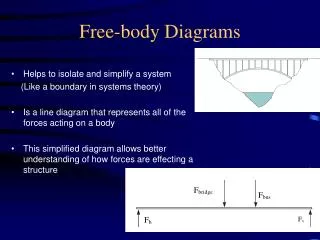
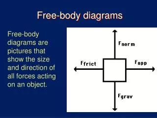
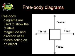
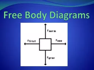
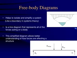
Free-body Diagrams • Helps to isolate and simplify a system (Like a boundary in systems theory) • Is a line diagram that represents all of the forces acting on a body • This simplified diagram allows better understanding of how forces are effecting a structure
B e a m s • Beams occur in almost every structure • They are subject to forces and turning moments • For a horizontal beam to be in equilibrium: • upwards forces = downwards forces • clockwise moments = anticlockwise moments
M M M M B e a m R e a c t i o n s • Beams are supported differently than levers • Common examples are shown below: Built in Simple Built in at 1 end only Built in and simple
Example • Determine the reactions R1 and R2 for the following simply supported beam
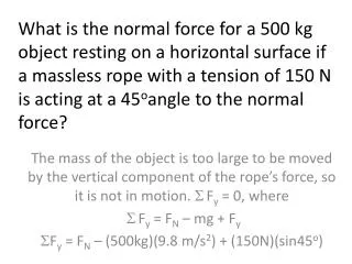
Take moments about R1 clockwise moments = anticlockwise moments (10,000 N 2 m) + (500 N 2.5 m) + (6000 N 4 m) = R2 5 m R2 = 20,000 Nm + 1250 Nm + 24,000 Nm = 9050N 5 m Also upwards forces = downwards forces R1 + 9050 N = 10,000 N + 500 N + 6000 N R1 = 16,500 N – 9050 N= 7450 N Therefore the reactions for the beam supports are R1 = 7450 N and R2 = 9050 N
LINKAGES • Levers are often linked together to transmit force or motion. A linkage consists of two or more levers connected together. Linkages are useful for changing the direction of an input or for giving greater force or distance amplifications.
LINKAGES • TASK: • Open up the mechanisms software program • Find the Likages section from the menu • Construct a revision sheet based on the information given in this section • Remember to add sketches
Linkages Linkages are an essential part of many mechanisms. They can be used to change direction, alter speed and change the timing of moving parts.In this example two linked linkages are used to convert the small linear movement of the drive shaft (bottom left) into first a rotational body movement and secondly a fast hammer movement. Compare the speed of the hammer with the speed of the drive shaft!
Linkages • The basic 4 bar linkage. All four bars make up a parallelogram. Two, equal length orange shafts and the distance between the joints on the red moving bar and yellow fixed bar being equal. The movement of the top arrange shaft exactly shadows the movement of the lower orange bar.By changing these lengths and the lengths of the other bars different movements can be achieved.
Linkages • This time, two different lengths of bar, the two long bars, yellow and red are the same length as before.Look at the tip of the red shaft, notice how it moves smothly until the last second then flips to the right.
Linkages • Quite an extreme arrangement this! With the two long bars crossing over each other. A more extreme 'kick' in the orange bar this time at the end of the green bar's travel. Looks like a likely mechanism for a model!
Linkages • http://www.robives.com/mechs Have a look at this web site and try to find others which discuss linkages. Then construct a revision aid on linkages.