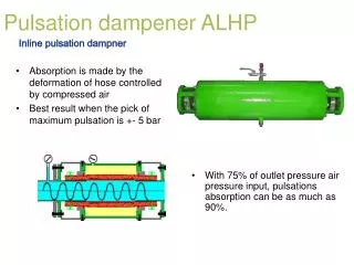
Pulsation Damper
Pulsation Damper. Fuel System Diagnosis. Fuel System Requirements. The fuel system must be able to maintain a consistent supply of fuel to the engine If the engine is receiving either more or less fuel than required, engine performance will suffer. Air/Fuel Ratio.
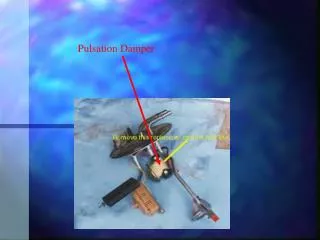

Pulsation Damper
E N D
Presentation Transcript
Fuel System Requirements • The fuel system must be able to maintain a consistent supply of fuel to the engine • If the engine is receiving either more or less fuel than required, engine performance will suffer
Air/Fuel Ratio • The stoichiometric air/fuel ratio is 14.7:1 • A higher ratio (meaning more air or less fuel) is considered a lean condition • A lower ratio (meaning less air or more fuel) is considered a rich condition
Possible Causes of a Lean Condition (Carbureted) • Low fuel pressure/volume • Weak fuel pump • Blocked fuel filter • Pinched fuel line • Faulty fuel pressure regulator (if used) • Improper jets • Improper float level • Dirty fuel circuits within the carburetor
Possible Causes of a Lean Condition (Fuel Injection) • Low fuel pressure/volume • Weak fuel pump • Blocked fuel filter • Pinched fuel line • Faulty fuel pressure regulator • ECM improperly controlling fuel due to: • Faulty oxygen sensor (O2) • Faulty mass airflow sensor (MAF) • Faulty manifold absolute pressure sensor (MAP) • Faulty throttle position sensor (TPS) • Faulty engine temperature sensor (ECT, CTS) • Faulty intake air temperature sensor (IAT) • Faulty fuel injector • Dirty • Electrically faulty
Possible Causes of a Rich Condition (Carbureted) • High fuel pressure/volume • Faulty fuel pressure regulator (if used) • Improper pump • Blocked air bleeds • High float level • Improper jets • Faulty or misadjusted choke • Leaking gasket • Leaking main well plugs (Quadrajet)
Possible Causes of a Rich Condition (Fuel Injection) • High fuel pressure/volume • Pinched return fuel line • Faulty fuel pressure regulator • ECM improperly controlling fuel due to: • Faulty oxygen sensor (O2) • Faulty mass airflow sensor (MAF) • Faulty manifold absolute pressure sensor (MAP) • Faulty throttle position sensor (TPS) • Faulty engine temperature sensor (ECT, CTS) • Faulty intake air temperature sensor (IAT) • Faulty fuel injector • Pintle leaking • Mechanically faulty
Testing • Fuel pressure test • Checks fuel pump for proper pressure • Checks fuel pressure regulator for proper operation • Fuel volume test • Checks fuel pump, lines, filter ,etc. For proper flow rate • Even if there is proper pressure at idle, at WOT there may be enough restriction due to a clogged filter etc. To cause a drop in pressure • Injector balance test
Fuel Pressure Test • Relieve fuel pressure • Pull fuel pump fuse and crank • Replace fuse • Hook the fuel pressure gauge up to the pressure line of the fuel system (use a rag to catch any fuel spillage) • Tee into the line • Attach gauge to the Schrader valve • Look up testing procedures for particular vehicle • Key on test • Regulator test
Fuel Volume Test • Using the fuel pressure gauge, open the bleed valve while the engine is idling • Measure the amount of fuel that is pumped through, and the amount of time it took to flow • Compare to manufacturer’s specs • 1 pint in 30 seconds (rule of thumb)
Injector Balance Test • Used to compare the flow rates of each injector • Hook fuel pressure gauge and cycle the ignition key to energize fuel pump • Record the pressure • Cycle one injector and record the amount of pressure drop • Cycle the key to restore full pressure to the system • Repeat for each injector • Injectors should not deviate more than 1.5 PSI from the average drop
ECM Controls • On fuel injected and feedback carbureted systems, the ECM (engine control module) controls fuel delivery • The ECM uses various inputs to determine the amount of fuel that should be delivered
Engine Performance ECM Inputs (Sensors) • Crankshaft position sensor (RPM) • Oxygensensor (O2) • MAP sensor • MAF sensor • CTS • IAT sensor • TPS
Crankshaft Position Sensor (CKP) • Lets the ECM know how many rpm’s the engine is running at • Lets the ECM know when a piston is at TDC (SEFI) • May be located • In the block • Reluctor on crankshaft • In the distributor • On the rear of the block • Flywheel/flexplate is the reluctor (Dodge) • On the front of the block • Reluctor on the harmonic balancer • Separate reluctor
MAP sensor (Manifold Absolute Pressure) • Lets the ECM know what current manifold pressure (vacuum) is • Uses a strain gauge to produce a signal which the ECM can interpret as manifold vacuum
Oxygen Sensor (O2) • Compares the amount of oxygen in the exhaust to the amount of oxygen in the atmosphere • Produces its own voltage • The greater the difference in oxygen between the two, the more voltage is produced (0 volts – 1 volt) • ECM uses this signal as a rich/lean indicator
Throttle Position Sensor (TPS) • Lets the ECM know how much the throttle is being depressed • Generally located on throttle body • May be located on the accelerator pedal and the throttle indirectly operated by the ECM (Corvette and 6.5L turbo diesel) • Potentiometer
Coolant Temperature Sensor (CTS, ECT) • Lets the ECM know the current engine coolant temperature • Located in the head, intake, or thermostat housing
Intake Air Temperature Sensor (IAT) • Lets the ECM know what temperature the incoming air is • Located in the throttle body, air cleaner, or intake manifold
Mass Airflow Sensor (MAF) • Used to tell the computer the mass of the air entering the engine per revolution. • A heated wire is suspended in the incoming airstream, and the sensor monitors how much amperage is needed to maintain the temperature of the wire. • The more airflow (mass), the faster the wire is cooled, which requires more amperage to be passes through the wire to maintain the temperature. • The circuitry of the sensor calculates the airflow from this required amperage and sends a signal to the ECM telling it how much air is entering the engine. • Various styles of mass airflow sensors are used.
ECM Controls • To determine the amount of fuel required, the ECM needs to know how much air is entering the engine • Two methods for measuring airflow • Speed-Density • Mass Airflow
Speed-Density • The ECM receives input from • MAP (engine vacuum) • TPS (throttle position) • CTS (coolant temperature) • IAT (air temperature) • O2 (rich/lean indicator) • CKP (engine RPM)
Speed-Density • Based on the engine vacuum, engine rpm, intake air temperature, and the pre-programmed volumetric efficiency of the engine, the computer calculates the amount of air entering the engine • Engine operating temperature, throttle position, and rich/lean indications from the O2 are then used to calculate/adjust the required amount of fuel
Speed Density O2 CTS TPS MAP Airflow ECM ECM CKP IAT Injectors
Mass Airflow • Based on the airflow data received from the MAF engine operating temperature, throttle position, and rich/lean indications from the O2 are used to calculate/adjust the required amount of fuel
Mass Airflow O2 CTS TPS CKP Airflow ECM ECM MAF Injectors