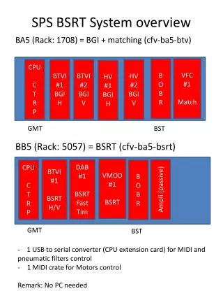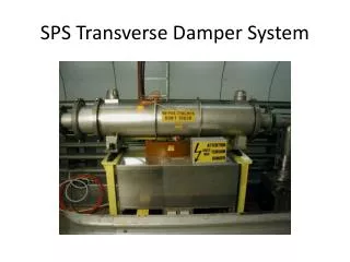
SPS Transverse Damper System
290 likes | 496 Vues
SPS Transverse Damper System. Overview. What is it used for ? How does it work ? Control and Diagnostics Electronic details. What is it used for ?. Damping of transverse injection errors Feedback: to cure transverse coupled bunch instabilities

SPS Transverse Damper System
E N D
Presentation Transcript
Overview • What is it used for ? • How does it work ? • Control and Diagnostics • Electronic details
What is it used for ? • Damping of transverse injection errors • Feedback: to cure transverse coupled bunch instabilities • Excitation of transverse oscillations for beam measurements (Multi-Q) and increase of emittance (blow up)
How does it work ? • A feedback loop including : • Pick-ups (2.04 => 2.15) Associated by pairs according to the beam type • A Low Level part (Signal process + Pick-up Mixing + Low Level) • 4 “electrostatic” kickers (H1, H2, V1 and V2) H1, H2 and V1 Installed in LSS2- V2 installed in LSS2+
Feedback Loop Beam deflector Position monitor BEAM + - Low Level Surface – BA2
Association of the Pick-ups Used as spares
The Pick-ups (position monitors) BDH 2.04 BDV 2.05 Shared with BI (MOPOS) but specific electronics
Simplified Block Diagram (H1 & H2) Closed orbit suppr. Delay adjust. 2 pick-ups 2.12 & 2.14 Fixed Target beam Damper H1 BDH 214.37 ( ) Timing ON/OFF External excitation • Pick-ups Mixing • Betatron phase adjust. Gain LSA D Level adjust. S Level adjust. Closed orbit suppr. Delay adjust. 2 pick-ups 2.04 & 2.06 LHC beam Timing ON/OFF External excitation Damper H2 BDH 214.51 ( ) Gain LSA D Level adjust. S Level adjust.
The electrostatic kickers BDH 214.37 (H1) BDH 214.51 (H2) BDV 214.57 (V1) BDV 221.76 (V2) LSS 2 + LSS 2 -
Control and Diagnostics • Control New RF Control Application (MMI) Trim Editor Application (LSA) • Diagnostics Oasis Application • Compare with reference signals
New RF Control Application • More ergonomic • All parameters readable • Role based access to change settings • Synoptic : Experts view / Simplified view for Operation
Block Diagram (H1 & H2) New MMI LSA 2.12 & 2.14 LSA New MMI 2.04 & 2.06 timing timing Multi-Q
Dampers H1 & H2 (simplified) 2 pick-ups 2.12 & 2.14 Fixed Target beam Damper H1 BDH 214.37 ( ) Closed orbit suppr. (Notch Filter) Delay adjust. Timing ON/OFF External excitation Level adjust ‘DGCA’ • Pick-ups Mixing • ‘DPUM’ • - p.u. select • - Polarity • Phase • Betatron phase adjust. Gain LSA D Level adjust ‘DGCA’ S 2 pick-ups 2.04 & 2.06 LHC beam Closed orbit suppr. (Notch Filter) Delay adjust. Timing ON/OFF External excitation Damper H2 BDH 214.51 ( ) Level adjust ‘DGCA’ Gain LSA D Level adjust ‘DGCA’ S - Controlled by the new MMI application - Controlled by LSA (Trim Editor Application)
Diagnostics • Observation with OASIS Application: • Delta : difference between the signals of one pick-up (= not normalised transverse position of the beam position * Intensity) • Sum : sum of the signals of one pick-up (= intensity of the beam) • Input : signal leaving the low level • Plates : voltage of the kicker’s plates (= delta signal between the two plates)
Diagnostics Sum Delta Input Plates
Diagnostics • Delta signals + BCT (100ms/div) • 2.13V and 2.15V (CNGS beam – Damper V)
Diagnostics • Sum signals (100ms/div) • 2.13V and 2.15V (CNGS beam – Damper V)
Diagnostics • Input V2 and Plates V2 signals (100ms/div)
Few more details.. • How the signals are treated in the electronic part of the system ?
2.04 D and 2.06 D – H plane(LHC Beam - Single Bunch, scope in SR4)
Pick-up Mixing Main * cos F Aux * sin F Betatron phase advance between p.u. and the kicker has to be = 90°
Pick-up Mixing Vector sum Aux. pu D F Main pu D Vector sum = Main*cos F + Aux*sin F Betatron phase adjustment is done by combining 2 “orthogonal” (~ 88°) signals with good signs and good ratios
Low Level • Notch Filter does the difference between 2 turns delete the closed orbit • Delay is to ensure that the signal arrives at the kicker at the right time (right bunch) • (Delay = Dt + temps de vol du signal) • LSA Gain to be adjusted with the Energy of the Beam (damping time & losses)
Feedback Loop Beam deflector Position monitor BEAM Low Level Surface – BA2 1st turn: Measurements only 2nd turn: Meas + correct but with orbit offset 3rd turn: Correction OK