Download
1 / 25
250 likes | 409 Vues
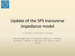
Update of the SPS transverse impedance model. C. Zannini, G. Rumolo, B. Salvant Acknowledgments: H. Bartosik, O.Berrig , F. Caspers, E. Chapochnikova, G. Iadarola, E. M é tral , N. Mounet , V.G. Vaccaro, J. E. Varela. SPS transverse impedance model. Elements included in the database:

E N D
Update of the SPS transverse impedance model C. Zannini, G. Rumolo, B. Salvant Acknowledgments: H. Bartosik, O.Berrig, F. Caspers, E. Chapochnikova, G. Iadarola, E. Métral, N. Mounet, V.G. Vaccaro, J. E. Varela
SPS transverse impedance model • Elements included in the database: • 106 BPHs (CST 3D simulations) • 96 BPVs (CST 3D simulations) • 200 MHz cavities without couplers (CST 3D simulations) • 800 MHz cavities without couplers (CST 3D simulations) • Wall impedance that takes into account the different SPS vacuum chambers (analytical calculations) • 19 kickers (CST 3D simulation) • Broadband impedance of the flanges (CST 3D simulations) TW 200MHz and 800MHz BPV BPH Beam pipe Kickers Flanges
SPS transverse impedance model Peaks due to the serigraphy of the extraction kickers
SPS transverse impedance model Broadband impedance from kickers, flanges and resistive wall
SPS transverse impedance model Peaks due to the RF system and BPMs
SPS transverse impedance model • Benchmark with beam measurements • Tune shift • Instability behavior
Benchmark of the SPS impedance model: tune shift measurements Vertical coherent tune shift: Measurements performed in September 2012 20 % 40 % 60 % 80 % 100 % The SPS impedance model explains more than 90% of the measured vertical coherent tune shift
Benchmark of the SPS impedance model: tune shift measurements Horizontal coherent tune shift: Measurements performed in February 2013 The SPS impedance model predicts a very small horizontal tune shift (almost flat) in agreement with the measurements
Benchmark of the SPS impedance model: instability behavior H. Bartosik • Two regimes of instability in measurements • Fast instability threshold with linear dependence on εl • Slow instability for intermediate intensity and low εl • Very well reproduced with HEADTAIL simulations • SPS impedance model includes kickers, wall, BPMs and RF cavities • Direct space charge not included measurements HEADTAIL simulations nominal Island of slow instability 4.5x10¹¹p/b @ 0.35 eVs
New elements to be added in the model • Simulations are ongoing or must be finalized • Septa • Wire scanner • Non standard elements (special transitions, valves) • Update due to future installations and modifications • New wire scanner • New kicker for high bandwidth feedback system • New MSI-V septum • Serigraphy of the last MKE (7/8 were already serigraphed in the 2012)
Evolution of the extraction kickers in the SPS 2014 8 8 Post-LS1
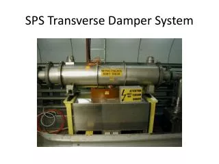
Realistic models: SPS extraction kicker (MKE-L) Serigraphy Seven out of eight SPS extraction kickers have been serigraphed F. Caspers, T. Kroyer, M. Barnes, E. Gaxiola et al.
Comparing MKE with and without serigraphy The peak observed in the MKE with serigraphy is a quarter-wavelength resonance on the finger length
Evolution of the extraction kickers in the SPS: vertical tune shift Kickers play a major role in the SPS total impedance The trend of the vertical effective impedance along the last 10 years is in good agreement with the expected changing of the kicker impedance model
Evolution of the extraction kickers in the SPS: horizontal tune shift Kickers play a major role in the SPS total impedance The trend of the horizontal effective impedance along the last 10 years is in good agreement with the expected changing of the kicker impedance model
Intra-bunch motion:Q20 H. Bartosik measurements HEADTAIL simulations Example for slow instability Example for fast TMC instability • Excellent agreement between measurements and simulation
Broadband impedance of step transitions The imaginary part of the transverse impedanceisweaklydependent on the cavitylengthbelow 1 GHz b = 17. 25 mm d = 78 mm For the main SPS cavitylike structures the first resonating mode isabove 1 GHz (r<80 mm) L2
Broadband impedance of step transitions L2 Weak dependence on L2
Broadband impedance of step transitions Courtesy of Jose E. Varela
Pumping ports Impedance reduction campaign: shielding of the pumping ports, lepton cavities etc.) 2000 Total number of shielded pumping ports H. Burkhardt, G.Rumolo, F. Zimmermann: Measurements of SPS Single-Bunch coherent Tune Shifts and Head-Tail Growth Rates in the Year 2001 P. Collier et al.: Reducing the SPS Machine Impedance, 2002 The broadband impedance due to step transitions can give significant contribution to the coherent tune shift
Pumping ports Impedance reduction campaign: shielding of the pumping ports, lepton cavities etc.) 2000 SPS Pumping port SPS Pumping port shielding The picture does not include pumping holes
Estimation of the broadband impedance of unshielded transitions between magnets and straight sections Bending magnets • 744 step-in step-out transitions: • 377 MBA-Straight A • 377 MBB-Straight B