Download
1 / 1
10 likes | 119 Vues
Explore how Multi-Bit Differential Signaling (MBDS) extends signaling capabilities for enhanced channel density. Learn about layout design, simulation results, and challenges faced in next-gen signaling solutions.

E N D
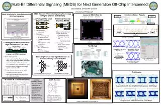
Need Solutions for High-Performance Off-Chip Signaling 2c1 input 2c1 output 4c2 output 4c2 input Layout of MBDS Test Die Bias input Simulation Setup / Results Bias input Extracted netlists Extracted netlists Extending Current-Steering LVDS drivers to Support Arbitrary Channel Widths Sample inputs Source: Intel Corporation MBDS Extends Differential Signaling Technology for Higher Channel Code Density 2-wire Differential (2c1) Driver 4-wire MBDS (4c2) Driver Low Voltage Differential Signaling (LVDS) Multi-Bit Differential Signaling (MBDS) Challenges for Next Generation High Performance Off-Chip Signaling “N choose M” Channel Encoding Test Setup EXAMPLE 6-wire MBDS channel code size = 20 codes effective bits = 4 equivalent to 8-wire differential channel 25% fewer pads (8 versus 6) 25% less power (4 1-bits on versus 3) 125% code capacity (20 codes versus 16) Packaged chip Packaged chip PCB trace 2c1 channel at 1 Gbps, 500 bit times, scale +/- 1 V 4c2 channel at 1 Gbps, 500 bit times, scale +/- 600mV • Data encoded as • {01} or {10} • Advantages • Low switching noise • No reference noise • Coupled transmission lines • Noise rejection => low voltage swing • Disadvantages • Two connections for each bit • Wasteful in I/O pads Ground plane • Data encoded with fixed number of one-bits • N-choose-M (nCm) • Example: 4c2 code set: • {0011}, {0101}, {0110}, {1001}, {1010}, {1100} • Advantages • Same noise rejection as differential • Higher information capacity Example Chip-to-Chip Interconnect Eye plots show no significant loss of signal integrity as MBDS channel width is scaled up • Signal integrity issues • High metal content of off-chip signaling paths contain capacitance and inductance creating low-pass frequency response • Off-chip signals highly susceptible to noise • Synchronization difficult for high-speed signals due to skew/jitter • Off-chip channels must be narrow / serial • I/O pads a precious resource • High-speed drivers must be large due to skin effect (real estate) 8c4 channel at 1 Gbps, 500 bit times, scale +/- 600mV Test Results Chip Package Model Code set size Outputs from Off-the-Shelf LVDS Receiver, 200 Mbps LVDS Receiver solder bump model solder bump model wire bond model Effective bits Outputs from MBDS Receiver, 500 Mbps PCB Transmission Line Model Parameters LVDS receiver design from: Stefan Hirsch, Hans-Jörg Pfleiderer, “CMOS receiver circuits for high-speed data transmission according to LVDS-standard,” Proceedings of SPIE Vol. 5117 (2003). Images of fabricated and packaged die Multi-Bit Differential Signaling (MBDS) for Next Generation Off-Chip Interconnect Jason Bakos, Donald M. Chiarulli University of Pittsburgh