Download

1 / 35
360 likes | 548 Vues
Joint Institute for Nuclear Research. Further optimization of the solenoid design. A.Efremov, E.Koshurnikov, Yu.Lobanov, A.Makarov, A.Vodopianov GSI, Darmstadt, 05.03.2008. Coil and yoke dimensions. Barrel part 1490 mm < r < 2300 mm 60 mm + 11×30 mm + 60 mm steel; 12 gaps of 30 mm

E N D
Joint Institute for Nuclear Research Further optimization of the solenoid design A.Efremov, E.Koshurnikov, Yu.Lobanov, A.Makarov, A.Vodopianov GSI, Darmstadt, 05.03.2008
Coil and yoke dimensions • Barrel part • 1490 mm < r < 2300 mm • 60 mm + 11×30 mm + 60 mm steel; 12 gaps of 30 mm • Upstream door • Upper radius: -1970 mm < z < -1585 mm • Lower radius: -1970 mm < z < -1734 mm • Downstream door • 2465 mm < z < 2865 mm • 5×60 mm steel; 4 gaps of 25 mm • Cryostat • -1190 mm < z < 1900 mm • Gaps between the coil and cryostat ends: • 170 mm (upstream) and 155 mm (downstream) • In ZEUS: both gaps are 150 mm
Solenoid cross-section Side view
Solenoid cross-section Top view
Magnetic flux density distribution The flux density in the upstream door is B < 1.7 T and the flux density near it in the downstream direction is B < 1 T.
Field homogeneity B0 = 2T |δ| < 1.78%
Radial component integral |Iup| < 1.72 mm
Dependence of parameterson the coil position Coil configuration is defined using our computer code
Impact of the cable passages across the barrel part of solenoid 800 x 60 mm2 at the octagon corners both at the upstream and downstream barrel ends Axisymmetric model: use of effective magnetic permeability fill factor: Stotal and Ssteel – cross-sections of barrel beam and its steel part in the plane crossing the gaps perpendicular to Z The calculations are not sensitive to the place of the gap on this plane
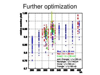
Impact of the cable passages across the barrel part of solenoid
Impact of the cable passages across the barrel part of solenoid The passages have small influence on the homogeneity and field integral in central region
Stress-strain analysisdownstream door, inner (first) plate ΔZ < 0.05 mm Fixation scheme Axial displacement [m]
0 1 Stress-strain analysisdownstream door (second plate) Axial displacement [m]
Stress-strain analysisdownstream door (second plate) Fixation scheme
Stress-strain analysisdownstream door (second plate) Equivalent stress (Von Mises) σ < 25 MPa 3 welded spacers Allowable value: [σ] = 140 MPa
Stress-strain analysisupstream door The door consists of 8 steel plates of 30 mm thickness consolidated in a package Equivalent stress (Von Mises) σ < 3 MPa
0 1 Stress-strain analysisupstream door Maximal axial displacement ΔZ < 0.5 mm
Beam deformationin thecross-section With outer frames gravity loadand Px = 0.25 G, Py = 0.18 G (seismic load) Yoke barrelgravity load G = 2000 kN Maximal value of the deformation: uy = 1.5 mm, ux = ± 1 mm Maximal value of the deformation: uy = 1.6 mm, ux = 2 mm Maximal stress σmax = 35 MPa Maximal stress σmax = 50 MPa
Al cylinder subcoil 1 subcoil 2 subcoil 3 subcoil 25 mm Al with slits (for shear stress reduction) solid Al Solenoid coil
Solenoid coil Shear stress at the subcoil end face < 5 MPa 1 subcoil 0 solid Al
Design criteria for the solenoid structural parts produced from metal alloys are chosen in accordance with “Codes of design to calculate the strength of equipment and pipe-lines of nuclear power plants” PNAE-G-002-86 and “Codes of strength calculations for high pressure vessels” (GOST 1429-89). Design criteria for the yoke and support frames include building norms and codes for steel constructions (Russian) and Eurocodes 3 . Allowable membrane stress in a solenoid structural part in the normal operation regime has to be chosen as follows: where safety coefficients (safety margins) for the coil are and for the yoke are Allowable bending stress in a structural part in the normal operation regime has to be chosen as follows: Mechanical analysis
Beam deformationin thecross-section Without outer frames gravity loadand Px = 0.25 G, Py = 0.18 G (seismic load) Yoke barrelgravity load G = 2000 kN Maximal value of the deformation: uy = 4.3 mm, ux = ± 2.5 mm Maximal value of the deformation: uy = 5.8 mm, ux = 9.6 mm Maximal stress σmax = 115 MPa Maximal stress σmax = 140 MPa