
The IS-IS Protocol
E N D
Presentation Transcript
The IS-IS Protocol Introducing IS-IS and Integrated IS-IS Routing
Uses for IS-IS Routing • Large ISPs • Stable protocol • Originally deployed by ISPs because U.S. government mandated Internet support of OSI and IP
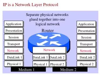
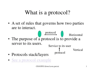
IS-IS Routing • IS = router. • IS-IS was originally designed as the IGP for the Connectionless Network Service (CLNS), part of the OSI protocol suite. • The OSI protocol suite layer 3 protocol is the Connectionless Network Protocol (CLNP). • IS-IS uses CLNS addresses to identify routers and build the LSDB.
IS-IS Features • Link-state routing protocol • Supports VLSM • Uses Dijkstra’s SPF algorithm; has fast convergence • Uses hellos to establish adjacencies and LSPs to exchange link-state information • Efficient use of bandwidth, memory, and processor • Supports two routing levels: • Level 1: Builds common topology of system IDs in local area and routes within area using lowest cost path. • Level 2: Exchanges prefix information (area addresses) between areas. Routes traffic to area using lowest-cost path.
IS-IS Link-State Operation • Routers are identified as Level 1, Level 2, or Level 1-2: • Level 1 routers use LSPs to build topology for local area. • Level 2 routers use LSPs to build topology betweendifferent areas. • Level 1-2 routers act as border routers between Level 1 and Level 2 routing domains.
Integrated (or Dual) IS-IS Routing • Integrated IS-IS is IS-IS for multiple protocols: • For IP, CLNS, or both • Uses its own PDUs to transport IP routing information; updates not sent in IP packets • Requires CLNS addresses, even if only routing for IP
Issues with Integrated IS-IS • Default narrow metrics are limited to 6-bit interface and 10-bit path metric • In Cisco IOS Software Relase 12.0, wide metrics allow 24-bit interface and 32-bit path metric. • Cisco IOS software has default metric of 10 on all interfaces.
Similarities Between IS-IS and OSPF • Integrated IS-IS and OSPF are both open standard link-state protocols with the following similar features: • Link-state representation, aging timers, and LSDB synchronization • SPF algorithms • Update, decision, and flooding processes • VLSM support • Scalability of link-state protocols has been proven (used in ISP backbones). • They both converge quickly after changes.
OSPF is based on a central backbone with all other areas attached to it. In OSPF the border is inside routers (ABRs). Each link belongs to one area. Integrated IS-IS vs.OSPF: Area Design
In IS-IS the area borders lie on links Each IS-IS router belongs to exactly one area. IS-IS is more flexible when extending the backbone. Integrated IS-IS vs.OSPF: Area Design (Cont.)
Advantages of Integrated IS-IS • Supports CLNP, IP, IPv6 • More extensible through TLV design
Advantages of OSPF • OSPF has more features, including: • Has three area types: normal, stub, and NSSA • Defaults to scaled metric (IS-IS always 10) • OSPF is supported by many vendors. • Information, examples, and experienced engineers are easier to find.
The IS-IS Protocol Performing IS-IS Routing Operations
OSI Addresses • OSI networklayer addressing is implementedwith NSAP addresses. • An NSAP address identifies a systemin theOSI network; an address represents an entire node, not an interface. • Various NSAP formats are used in various systems, because different protocols may use different representations of NSAP. • NSAP addresses are a maximum of 20 bytes: • Higher-order bits identify the interarea structure. • Lower-order bits identify systems within area.
Typical NSAP Address Structure • The simplest NSAP format used by most companies running IS-IS as their IGP is as follows: • Area address (must be at least 1 byte) • AFI set to 49 • Locally administered; thus, you can assign your own addresses. • Area ID • The octets of the area address after the AFI. • System ID • Cisco routers require a 6-byte system ID. • NSEL • Always set to 0 for a router.
The area address uniquely identifies the routing area, and the system ID identifies each node. All routers within an area must use the same area address. An ES may be adjacent to a router only if they share a common area address. Area addressis used in Level 2 routing. Identifying Systems in IS-IS: Area Address
Identifying Systemsin IS-IS: System ID • System ID in the address used to identify the IS; it is not just an interface. Cisco supports only a 6-byte system ID. • System ID is used in Level 1 routing and has to be unique within an area. • System ID has to be unique within Level 2 routers that form the routing domain. • General recommendation: use domain-wide unique system ID. • This may be MAC (for example, 0000.0c12.3456) or IP address (for example, 1921.6800.0001) taken from an interface.
OSI Addressing: NET Addresses • NSAP address includes NSEL field (process or port number) • NET: NSAP with a NSEL field of 0 • Refers to the device itself (equivalent to the Layer 3 OSI address of the device) • Used in routers because they implement the network layer only (base for SPF calculation)
Subnetwork Point of Attachment (SNPA)and Circuit • SNPA is equivalent to Layer 2 address; for example: • Virtual circuit ID (DLCI on Frame Relay) • MAC address on LAN interfaces • Interfaces uniquely identified by circuit ID: • On point-to-point interfaces, SNPA is used. • On LANs, circuit ID concatenated with six-octet system ID of a designated IS to form seven-octet LAN ID (for example, 1921.6800.0001.01) is used. • Cisco routers use host name instead of system ID (for example, “R1.01”).
Level 1, Level 2, and Level 1-2 Routers • Level 1 (like OSPF internal nonbackbone routers): • Intra-area routing enables ESs to communicate. • Level 1 area is a collection of Level 1 and Level 1-2 routers. • Level 1 IS keeps copy of the Level 1 area LSDB. • Level 1-2 (like OSPF ABR): • Intra-area and interarea routing. • Level 1-2 IS keeps separate Level 1 and Level 2 LSDBs and advertises default route to Level 1 routers. • Level 2 (like OSPF backbone routers): • Interarea routing. • Level 2 (backbone) area is a contiguousset of Level 1-2 and Level 2 routers. • Level 2 IS keeps a copy of the Level 2 area LSDB.
Addressing and Routing • Area address is used to route between areas; system ID is not considered. • System ID is used to route within an area; area address is not considered.
OSI IS-IS Routing Logic • Level 1 router: For a destination address, compare the area address to this area. • If not equal, pass to nearest Level 1-2 router. • If equal, use Level 1 database to route by system ID. • Level 1-2 router: For a destination address, compare the area address to this area. • If not equal, use Level 2 database to route by area address. • If equal, use Level 1 database to route by system ID.
LSP Flooding • Single procedure for flooding, aging, and updating of LSPs. • Level 1 LSPs are flooded within an area. • Level 2 LSPs are flooded throughout the Level 2 backbone. • Large PDUs are divided into fragments that are independently flooded. • Each PDU is assigned an LSP fragment number, starting at 0 and incrementing by 1. • Separate LSDBs are maintained for Level 1 and Level 2 LSPs.
The IS-IS Protocol Configuring Basic Integrated IS-IS
Simple Integrated IS-IS Example The configured router acts as an IP-only Level 1-2 router. interface FastEthernet0/0 ip address 10.1.1.2 255.255.255.0 ip router isis ! interface Serial 0/0/1 ip address 10.2.2.2 255.255.255.0 ip router isis ! <output omitted> router isis net 49.0001.0000.0000.0002.00
Example: Tuning IS-IS Configuration • Change router type on R1 and R3. • Change interface levels on R2. • Change metric on S0/0/1.
Example: Are There Any IP Routes? router# show ip route [address [mask]] | [protocol [process-id]] R2#show ip route isis 10.0.0.0/24 is subnetted, 5 subnets i L2 10.30.30.0 [115/45] via 10.2.2.3, Serial0/0/1 i L1 10.10.10.0 [115/20] via 10.1.1.1, FastEthernet0/0 R2# Displays the current state of the routing table
TroubleshootingCommands: CLNS Router# show clns • Displays information about the CLNS network Router# show clns [area-tag]protocol • Lists the protocol-specific information Router# show clns interface [typenumber] • Lists the CLNS-specific information about each interface Router# show clns [area-tag] neighbors [type number] [detail] • Displays both ES and IS neighbors
Router# show isis [area-tag]route • DisplaysIS-IS Level 1 routing table (system IDs) (requires that CLNS routing be enabled) Router# show clns route [nsap] • Displays IS-IS routing table (areas) Router# show isis [area-tag] database • Displaysthe IS-IS LSDB Router# show isis [area-tag] topology • Displays IS-IS least-cost paths to destinations TroubleshootingCommands: CLNS and IS-IS
Example: OSI Intra-Area andInterarea Routing Routing in a Two-Level Area Structure
Level1 and Level 2 Topology Table R1#show isis topology IS-IS paths to level-1 routers System Id Metric Next-Hop Interface SNPA R1 -- R2 10 R2 Fa0/0 0016.4650.c470 R2#show isis topology IS-IS paths to level-1 routers System Id Metric Next-Hop Interface SNPA R1 10 R1 Fa0/0 0016.4610.fdb0 R2 -- IS-IS paths to level-2 routers System Id Metric Next-Hop Interface SNPA R1 ** R2 -- R3 35 R3 Se0/0/1 *HDLC*
Simple Troubleshooting:What About CLNS Protocol? R2# show clns protocol IS-IS Router: <Null Tag> System Id: 0000.0000.0002.00 IS-Type: level-1-2 Manual area address(es): 49.0001 Routing for area address(es): 49.0001 Interfaces supported by IS-IS: Loopback0 - IP Serial0/0/1 - IP FastEthernet0/0 - IP Redistribute: static (on by default) Distance for L2 CLNS routes: 110 RRR level: none Generate narrow metrics: level-1-2 Accept narrow metrics: level-1-2 Generate wide metrics: none Accept wide metrics: none
Are Adjacencies Established? R2# show clns neighbors System Id Interface SNPA State Holdtime Type Protocol R3 Se0/0/1 *HDLC* Up 28 L2 IS-IS R1 Fa0/0 0016.4610.fdb0 Up 23 L1 IS-IS R2#show clns interface s0/0/1 Serial0/0/1 is up, line protocol is up Checksums enabled, MTU 1500, Encapsulation HDLC ERPDUs enabled, min. interval 10 msec. CLNS fast switching enabled CLNS SSE switching disabled DEC compatibility mode OFF for this interface Next ESH/ISH in 45 seconds Routing Protocol: IS-IS Circuit Type: level-2 Interface number 0x1, local circuit ID 0x100 Neighbor System-ID: R3 Level-2 Metric: 35, Priority: 64, Circuit ID: R2.00 Level-2 IPv6 Metric: 10 Number of active level-2 adjacencies: 1 Next IS-IS Hello in 5 seconds if state UP