Download
1 / 68
2.08k likes | 4.95k Vues
Construction and Working of I.C. Engine Prepared by: Nimesh Gajjar. steam engines. external combustion. turbines. Stirling engine. Otto engine. internal combustion. Diesel engine. Vankel engine. Internal Combustion Engines. types of heat engines. Internal Combustion Engine Basics. air.

E N D
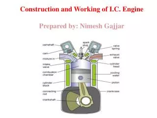
Construction and Working of I.C. Engine Prepared by: Nimesh Gajjar
steam engines external combustion turbines Stirling engine Otto engine internal combustion Diesel engine Vankel engine Internal Combustion Engines types of heat engines
Internal Combustion Engine Basics air Slide 01 D. Abata
pressure force pressure = area pressure x area force = Internal Combustion Engine Basics air Slide 02 D. Abata
pressure force pressure = area pressure x area force = Internal Combustion Engine Basics air + fuel Slide 03 D. Abata
Internal Combustion Engines The internal combustion engine is an engine in which the combustion of fuel-oxidizer mixture occurs in a confined space applied in: automotive rail transportation power generation ships aviation garden appliances
Combustion Engine Definiton Combustion engines are machines that deliver mechanical work through a linked thermal and combustion process: mechanical work is obtained from the chemical bound energy of the fuel (fuel energy) through combustion by means of thermal energy. In the reciprocating engines the working chamber has rigid walls: the stroke of one of the these walls (pistons) provides a variable volume. The work output is gained from the gas pressure
Engines Configuration • Engines: The cylinders are arranged in a line, in a single bank.
Engines Parts Valves: Minimum Two Valves pre Cylinder • Exhaust Valve lets the exhaust gases escape the combustion • Chamber. (Diameter is smaller then Intake valve) • Intake Valve lets the air or air fuel mixture to enter the • combustion chamber. (Diameter is larger than the exhaust valve)
Engines Valve Springs: Keeps the valves Closed. Valve Lifters: Rides the cam lobe and helps in opening the valves.
Engines Different arrangement of valve and camshaft.
Engines Cam Shaft: The shaft that has intake and Exhaust cams for operating the valves. Cam Lobe: Changes rotary motion into reciprocating motion.
Engines Spark Plug It provides the means of ignition when the gasoline engine’s piston is at the end of compression stroke, close to Top Dead Center(TDC) The difference between a "hot" and a "cold" spark plug is that the ceramic tip is longer on the hotter plug.
Engines Piston A movable part fitted into a cylinder, which can receive and transmit power. Through connecting rod, forces the crank shaft to rotate.
Engines Cylinder head Part that covers and encloses the Cylinder. It contains cooling fins or water jackets and the valves. Some engines contains the cam shaft in the cylinder head.
Engines Engine Block Foundation of the engine and contains pistons, crank shaft, cylinders, timing sprockets and sometimes the cam shaft.
Engines Connecting (conn.) Rod Attaches piston (wrist-pin) to the crank shaft (conn. rod caps).
Engines Crank Shaft Converts up and down or reciprocating motion into circular or rotary motion. DAMPNER PULLEY Controls Vibration
Engines Piston Rings Four stroke: Three rings Top two are compression rings (sealing the compression pressure in the cylinder) and the third is an oil ring (scrapes excessive oil from the cylinder walls) Two Stroke: Two Rings Both the rings are Compression rings.
Engines Flywheel Attached to the crankshaft Reduces vibration Cools the engine (air cooled) Used during initial start-up Transfers power from engine to drivetrain
Engine Related Terms • TDC (top dead center) • BDC (bottom dead center) • Stroke • Bore • Revolution • Compression Ratio • Displacement • Cycle
Nikolaus Otto was born in Holzhausen, Germany on 10th June 1832. In his early years he began experimenting with gas engines and completed his first atmospheric engine in 1867. In 1872 he joined with Gottlieb Daimler and Wilhelm Maybach and in 1876 developed the first 4-stroke cycle internal combustion engine based on principles patented in 1862 by Alphonse Beau de Rochas. Although Otto's patent claim for the 'Otto Cycle' was invalidated in 1886, his engineering work led to the first practical use of the 4-stroke cycle which was to provide the driving force for transportation for over a century. Nikolaus Otto died on 26th January 1891. Four-stroke Otto cycle
Four-stroke Otto cycle (Port injection/Indirect injection) Induction Stroke The induction stroke is generally considered to be the first stroke of the Otto 4-Stroke Cycle. At this point in the cycle, the inlet valve is open and the exhaust valve is closed. As the piston travels down the cylinder, a new charge of fuel/air mixture is drawn through the inlet port into the cylinder. The adjacent figure shows the engine crankshaft rotating in a clockwise direction. Fuel is injected through a sequentially controlled port injector just behind the inlet valve. Spark Ignition Spark ignition is the point at which the spark is generated at the sparking plug and is an essential difference between the Otto and Diesel cycles. It may also be considered as the beginning of the power stroke. It is shown here to illustrate that due to flame propagation delays, spark ignition timing commonly takes place 10 degress before TDC during idle and will advance to some 30 or so degrees under normal running conditions. Compression Stroke The compression stroke begins as the inlet valve closes and the piston is driven upwards in the cylinder bore by the momentum of the crankshaft and flywheel.
Four-stroke Otto cycle (Port injection/Indirect injection) Exhaust and Inlet Valve Overlap Exhaust and inlet valve overlap is the transition between the exhaust and inlet strokes and is a practical necessity for the efficient running of any internal combustion engine. Given the constraints imposed by the operation of mechanical valves and the inertia of the air in the inlet manifold, it is necessary to begin opening the inlet valve before the piston reaches Top Dead Centre (TDC) on the exhaust stroke. Likewise, in order to effectively remove all of the combustion gases, the exhaust valve remains open until after TDC. Thus, there is a point in each full cycle when both exhaust and inlet valves are open. The number of degrees over which this occurs and the proportional split across TDC is very much dependent on the engine design and the speed at which it operates. Power Stroke The power stroke begins as the fuel/air mixture is ignited by the spark. The rapidly burning mixture attempting to expand within the cylinder walls, generates a high pressure which forces the piston down the cylinder bore. The linear motion of the piston is converted into rotary motion through the crankshaft. The rotational energy is imparted as momentum to the flywheel which not only provides power for the end use, but also overcomes the work of compression and mechanical losses incurred in the cycle (valve opening and closing, alternator, fuel pump, water pump, etc.). Exhaust Stroke The exhaust stroke is as critical to the smooth and efficient operation of the engine as that of induction. As the name suggests, it's the stroke during which the gases formed during combustion are ejected from the cylinder. This needs to be as complete a process as possible, as any remaining gases displace an equivalent volume of the new charge of fuel/air mixture and leads to a reduction in the maximum possible power.
Four-stroke Otto cycle (Direct Injection) Otto Cycle Operation with Direct Injection The theoretical Otto Cycle process is the same for both indirect and direct fuel injection methods, but the efficiencies gained by using direct injection are bringing the practical application closer to the theoretical. Direct injection means that there is a total separation between the air and fuel required for combustion. This allows precise control over the quantity of fuel and the time in the cycle it is introduced into the cylinder. Thus, for maximum power (in similar manner to that of a port injection system), it is possible to inject a full quantity of fuel in the induction stroke, while for low load, maximum economy (lean-burn) operation it is possible to inject a smaller quantity of fuel during the compression stroke. Although lean-burn is implemented with indirect injection, the lean-burn misfire limit (point at which misfire occurs) is governed by the leanness of the fuel/air mixture in the cylinder. This limit is lowered in direct injection, spark ignition engines, as the fuel spray is directed towards the sparking plug to ensure that there is a chemically adequate mixture around the plug when the spark occurs.
Four-stroke Diesel cycle Rudolph Diesel was born in Paris of Bavarian parents in 1858. As a budding mechanical engineer at the Technical University in Munich, he became fascinated by the 2nd law of thermodynamics and the maximum efficiency of a Carnot process and attempted to improve the existing thermal engines of the day on the basis of purely theoretical considerations. His first prototype engine was built in 1893, a year after he applied for his initial patent, but it wasn't until the third prototype was built in 1897 that theory was put into practice with the first 'Diesel' engine.
Four-stroke Diesel cycle Compression Ignition Compression ignition takes place when the fuel from the high pressure fuel injector spontaneously ignites in the cylinder. In the theoretical cycle, fuel is injected at TDC, but as there is a finite time for the fuel to ignite (ignition lag) in practical engines, fuel is injected into the cylinder before the piston reaches TDC to ensure that maximum power can be achieved. This is synonymous with automatic spark ignition advance used in Otto cycle engines. Induction Stroke The induction stroke in a Diesel engine is used to draw in a new volume of charge air into the cylinder. As the power generated in an engine is dependent on the quantity of fuel burnt during combustion and that in turn is determined by the volume of air (oxygen) present, most diesel engines use turbochargers to force air into the cylinder during the induction stroke. Compression Stroke The compression stroke begins as the inlet valve closes and the piston is driven upwards in the cylinder bore by the momentum of the crankshaft and flywheel. The purpose of the compression stroke in a Diesel engine is to raise the temperature of the charge air to the point where fuel injected into the cylinder spontaneously ignites. In this cycle, the separation of fuel from the charge air eliminates problems with auto-ignition and therefore allows Diesel engines to operate at much higher compression ratios than those currently in production with the Otto Cycle.
Four-stroke Diesel cycle Power Stroke The power stroke begins as the injected fuel spontaneously ignites with the air in the cylinder. As the rapidly burning mixture attempts to expand within the cylinder walls, it generates a high pressure which forces the piston down the cylinder bore. The linear motion of the piston is converted into rotary motion through the crankshaft. The rotational energy is imparted as momentum to the flywheel which not only provides power for the end use, but also overcomes the work of compression and mechanical losses incurred in the cycle (valve opening and closing, alternator, fuel injector pump, water pump, etc.). Exhaust and Inlet Valve Overlap Exhaust and inlet valve overlap is the transition between the exhaust and inlet strokes and is a practical necessity for the efficient running of any internal combustion engine. Given the constraints imposed by the operation of mechanical valves and the inertia of the air in the inlet manifold, it is necessary to begin opening the inlet valve before the piston reaches Top Dead Centre (TDC) on the exhaust stroke. Likewise, in order to effectively remove all of the combustion gases, the exhaust valve remains open until after TDC. Thus, there is a point in each full cycle when both exhaust and inlet valves are open. The number of degrees over which this occurs and the proportional split across TDC is very much dependent on the engine design and the speed at which it operates. Exhaust Stroke The exhaust stroke is as critical to the smooth and efficient operation of the engine as that of induction. As the name suggests, it's the stroke during which the gases formed during combustion are ejected from the cylinder. This needs to be as complete a process as possible, as any remaining gases displace an equivalent volume of the new charge air and leads to a reduction in the maximum possible power.
Diesel vs Otto engine Advantages • Higher thermal efficiency as a consequence of a higher compression ratio (16-20 vs 9-12) needed for the self ignition of the mixture • Higher efficiency at part load condition (city driving) because of the different load control with much inferior pumping loss for aspirating air into the cylinder: load control directly by varying the fuel delivery, while in the Otto engine by varying the air through an intake throttle • Less energy spent to produce Diesel fuel Disadvantages • Higher weight for same power delivery, because of higher thermal and mechanical stresses due to higher temperatures and pressures , almost double vs Otto engine, at the end of compression and combustion phases • Lower maximum engine speed because a slower combustion process and higher weight of the rotating an oscillating masses • Engine roughness that generates higher structural and airborne vibration/noise.
Four Stroke Cycle • Intake • Compression • Power • Exhaust
Internal Combustion Engine Basics F Slide 04 D. Abata
Internal Combustion Engine Basics ignition system crank mechanism Slide 05 D. Abata
Internal Combustion Engine Basics intake system ignition system crank mechanism Slide 06 D. Abata
Internal Combustion Engine Basics intake system exhaust system ignition system crank mechanism Slide 07 D. Abata
Internal Combustion Engine Basics intake system exhaust system cooling system thermostat ignition system crank mechanism Slide 08 D. Abata
Internal Combustion Engine Basics intake system exhaust system cooling system thermostat ignition system lubrication system Slide 09 crankcase vent D. Abata
pressure volume TDC BDC Internal Combustion Engine Basics fuel air air + fuel 1. Intake Stroke Slide 10 D. Abata
pressure volume TDC BDC Internal Combustion Engine Basics stoichiometric mixture Slide 11 D. Abata
pressure volume TDC BDC Internal Combustion Engine Basics 2. Compression Stroke Slide 12 D. Abata
pressure volume TDC BDC Internal Combustion Engine Basics Slide 13 D. Abata
pressure volume TDC BDC Internal Combustion Engine Basics 3. Power Stroke Slide 14 D. Abata
pressure volume TDC BDC Internal Combustion Engine Basics Slide 15 D. Abata
pressure volume TDC BDC Internal Combustion Engine Basics 4. Exhaust Stroke Slide 16 D. Abata
pressure volume TDC BDC Internal Combustion Engine Basics Slide 17 D. Abata
pressure volume TDC BDC Internal Combustion Engine Basics Work = (pressure x volume) positive work 1. Intake Stroke exhaust gas residual negative work Slide 18 D. Abata
Intake Stroke • Intake valve opens. • Piston moves down, ½ turn of crankshaft. • A vacuum is created in the cylinder. • Atmospheric pressure pushes the air/fuel mixture into the cylinder.
Compression Stroke • Valves close. • Piston moves up, ½ turn of crankshaft. • Air/fuel mixture is compressed. • Fuel starts to vaporize and heat begins to build.
Power Stroke • Valves remain closed. • Spark plug fires igniting fuel mixture. • Piston moves down, ½ turn of crankshaft. • Heat is converted to mechanical energy.
Exhaust Stroke • Exhaust valve opens. • Piston move up, crankshaft makes ½ turn. • Exhaust gases are pushed out polluting the atmosphere.