Pass band data transmission
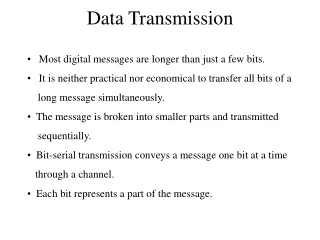
Pass band data transmission. In digital pass band data transmission the transmitted data bits are modulated onto a carrier There are three basic signaling schemes used in pass band these are Amplitude shift keying (ASK), the data bits modulates the amplitude of the carrier.

Pass band data transmission
E N D
Presentation Transcript
Pass band data transmission • In digital pass band data transmission the transmitted data bits are modulated onto a carrier • There are three basic signaling schemes used in pass band these are • Amplitude shift keying (ASK), the data bits modulates the amplitude of the carrier
Pass band data transmission • Frequency shift keying (FSK), the data bits modulates the frequency of the carrier • Phase shift keying (PSK), the data bits modulates the phase of the carrier • Those three keying schemes are illustrated graphically in next slide
Graphical representation of ASK, FSK and PSK ASK PSK FSK
Hierarchy of digital modulation techniques • Digital modulation techniques can be classifieds into • Coherent • Non coherent • This classification depends on whether the receiver contains a phase recovery or not
Hierarchy of digital modulation techniques In general coherent detection has a better immunity to noise but requires a complicated circuit compared with non coherent demodulation schemes
M-ary signaling schemes In many applications where the channel bandwidth is limited it is desired to transmit more than one bit using a single carrier Modulation schemes designed in this manner are called M-ary signaling scheme In pass band transmission these schemes are known as M-ary ASK, M-aryFSK and M-ary PSK
M-ary signaling schemes It is possible to generate M-ary signals by combining more than one modulation scheme such as amplitude and phase shift keying which is know as APK A special form of this hybrid modulation is M-ary quadrature amplitude shift keying (QAM)
Pass band Transmission model The pass band channel can be modeled as illustrated in the block diagram shown The main difference between pass band and base band model is the presence of modulator and demodulator (detector)
Geometric Representation of Modulation Signal • Digital Modulation involves • Choosing a particular signal waveform for transmission for a particular symbol or signal • For M possible signals, the set of all signal waveforms are: • For binary modulation, each bit is mapped to a signal from a set of signal set that has two signals • We can view the elements of as points in vector space
Geometric Representation of Modulation Signal Vector space We can represented the elements of S as linear combination of basis functions The number of basis functions are the dimension of the vector space Basis functions are orthogonal to each-other Each basis function is normalized to have unit energy
Geometric Representation of Modulation Signal Vector space The basis functions can be found by using a procedure called Gram-Schmidt procedure
Gram-Schmidt Procedure In this procedure the basis functions can be found as follows Find the first basis function
Coherent phase shift keying In coherent phase shift keying different phase modulation schemes will be covered iebinary PSK, quadrature phase shift keying and M-ary PSK Binary PSK will be studied in the next slides
Binary Phase shift keying In a coherent PSK system the pair of signals and are used to represent binary symbols 1 and 0
Binary Phase shift keying Where , and is the transmitted signal energy per bit The carrier frequency is selected such that so that each bit contains an integral number of cycles From the pair of symbols and we can see only one basis function (carrier) is need to represent both and
Binary Phase shift keying The basis function is given by Now we can rewrite and on the interval
Signal constellation for binary Phase shift keying If we plot the transmitted symbols for BPSK we may got the following constellation diagram
Signal constellation for binary Phase shift keying In order to draw the constellation diagram we need to find the projection of each transmitted symbol on the basis function The projection of the logic 1 is given by The projection of the second symbol on the basis function is given by
Error probability of BPSK In order to compute the error probability of BPSK we partition the constellation diagram of the BPSK (see slide 19) into two regions If the received symbol falls in region Z1, the receiver decide in favor of symbol S1 (1) was received If the received symbol falls in region Z2, the receiver decide in favor of symbol S2 (0) was received
Receiver model The receiver in the pass band can be modeled as shown The received signal vector
Error probability of BPSK The observable element (symbol zero was sent and the detected sample was read in zone 1) is given by
Error probability of BPSK To calculate the probability of error that symbol 0 was sent and the receiver detect 1 mistakenly we need to find the conditional probability density of the random variable , given that symbol 0, was transmitted as shown below
Error probability of BPSK The conditional probability of the receiver deciding in favor of symbol 1, given that symbol zero was transmitted is given by
Error probability of BPSK By letting the above integral for p10 can be rewritten as
Error probability of error In similar manner we can find probability of error that symbol 1 was sent and the receiver detect 0 mistakenly The average probability as we did in the baseband can be computed as This average probability is equivalent to the bit error rate
Generation of BPSK signals To generate a binary PSK signal we need to present the binary sequence in polar form The amplitude of logic 1 is whereas the amplitude of logic 0 is This signal transmission encoding is performed by using polar NRZ encoder
Generation of BPSK signals The resulting binary wave and the carrier (basis function) are applied to product multiplier as shown below
Detection of BPSK signals To detect the original binary sequence we apply the received noisy PSK signal to a correlator followed by a decision device as shown below The correlator works a matched filter
Power spectra of binary PSK signals The power spectral density of the binary PSK signal can be found as described for the bipolar NRZ signaling This assumption is valid because the BPSK is generated by using bipolar NRZ signaling
Power spectra of binary PSK signals The power spectral density can be found as