Filter123 Band Pass Filter
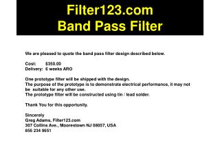
Filter123.com Band Pass Filter. We are pleased to quote the band pass filter design described below. Cost: $350.00 Delivery: 6 weeks ARO One prototype filter will be shipped with the design.

Filter123 Band Pass Filter
E N D
Presentation Transcript
Filter123.comBand Pass Filter We are pleased to quote the band pass filter design described below. Cost: $350.00 Delivery: 6 weeks ARO One prototype filter will be shipped with the design. The purpose of the prototype is to demonstrate electrical performance, it may not be suitable for any other use. The prototype filter will be constructed using tin / lead solder. Thank You for this opportunity. Sincerely Greg Adams, Filter123.com 307 Collins Ave., Moorestown NJ 08057, USA 856 234 9651
Pass Band Performance This table shows the maximum variation from unit to unit due to component value variations.
Stop Band Performance This table shows the maximum variation from unit to unit due to component value variations. Rejection is not specified below 50dB.
L1 L2 L3 C6 C12 C13 C7 IN C16 C4 C3 C2 C14 C15 C17 C11 C5 C8 C9 C10 OUT Schematic
Mesh1 Layout … Copper foil pattern for the band pass filter. The pattern to the left of the blue line is repeated as many times as needed. All traces are .020 inch wide.
A Foot Prints B C B A B C 1206 Inductor .076 .040 .070 0603 Capacitor .040 .044 .024
Irfan1 mesh … Copper foil pattern for the band pass filter, showing the placement of parts and pads. The inductors and capacitors are shown in YELLOW. The SMT pads for the parts are shown in BLUE.
D A B C E Part Locations … G F L H K S T N P Q R M Component X,Y coordinates locate the upper left corner of the copper land pattern for each component. The component placement pattern repeats every 0.436 inches. The first three components of the second repetition are shown to the left of the red dividing line. All components are situated on a .002 inch grid.