Download
1 / 18
180 likes | 362 Vues
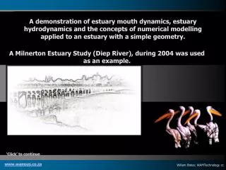
A demonstration of estuary mouth dynamics, estuary hydrodynamics and the concepts of numerical modelling applied to an estuary with a simple geometry. A Milnerton Estuary Study (Diep River), during 2004 was used as an example. ‘Click’ to continue. www.wamsys.co.za.

E N D
A demonstration of estuary mouth dynamics, estuary hydrodynamics and the concepts of numerical modelling applied to an estuary with a simple geometry. A Milnerton Estuary Study (Diep River), during 2004 was used as an example. ‘Click’ to continue www.wamsys.co.za Willem Botes: WAMTechnology cc
The inlet of the Milnerton Estuary……. Inlet ‘throat’ Estuary Sea The estuary inlet is the significant element for the controlling of the hydrodynamic behaviour of an estuary ‘Click’ to continue www.wamsys.co.za
The inlet of the Milnerton Estuary……. The inlet of the Milnerton estuary consists of a meandering channel, varying during river floods and extreme tidal events. The flow (velocity) in the inlet is a function of the water levels in the estuary and in the sea with external inflows (river flows) superimposed on it. When the estuary mouth closes, the mouth disappears and a ‘bar’ is formed (highest level of the sand bar is the sill). ‘Click’ to continue www.wamsys.co.za
The inlet processes at the Milnerton Estuary……. Estuary Beach Sea Tidal flows ………. Inflows (flood flows) …. ‘Click’ to continue www.wamsys.co.za
The inlet processes at the Milnerton Estuary……. Estuary Beach Sea Sediment transport into the estuary during inflows (flood flows) …. Flood ‘shoal’ is formed in the estuary ‘Click’ to continue www.wamsys.co.za
The inlet processes at the Milnerton Estuary……. Estuary Beach Sea Tidal flows ………. Outflows (ebb flows) …. …….. along the shoreline ……. ‘Click’ to continue www.wamsys.co.za
The inlet processes at the Milnerton Estuary……. Estuary Beach Sea Sediment transport from the estuary during out flows (ebb flows) …. Ebb ‘shoal’ is formed in the sea ‘Click’ to continue www.wamsys.co.za
Milnerton estuary ……. Sediment sources …. Fluvial TransportFrom the Diep River catchment. • Littoral Transport • The process of sediment moving along a coastline. This process has two components: LONGSHORE TRANSPORT and ONSHORE OFFSHORE TRANSPORT. Onshore-Offshore TransportThe up and down movement of sediment roughly perpendicular to a shoreline because of wave action Stormwater runoff Milnerton inlet to estuary Longshore TransportThe transport of sediment in water parallel to the shoreline. ‘Click’ to continue www.wamsys.co.za
Milnerton estuary ……. “Water supply” to the estuary …. Diep River Potsdam WWTW Tidal flows ‘Click’ to continue www.wamsys.co.za
Milnerton estuary ……. The hydrodynamic flushing of the estuary …. The exchange of water in an estuary, is generally referred to as the term Tidal Prism: Volume of water that flows into a tidal channel and out again during a complete tide, excluding any upland discharges The volume of water present between mean low and mean high tide. O’Brien (1931) provided a relationship between the Tidal Prism and the cross-sectional area of the inlet (using data from numerous estuaries), which provide a ‘ball-park’ answer to the stability/non-stability of an estuary inlet. ‘Click’ to continue www.wamsys.co.za
Milnerton estuary ……. The hydrodynamic flushing of the estuary …. O’Brien (1936): Tidal Prism vs cross-sectional area data ……. > 90% of stable tidal inlets Milnerton ‘Click’ to continue www.wamsys.co.za
The functioning of an estuary ……. The saline conditions in Milnerton estuary …. Historically, the Milnerton estuary was closed during dry summer months and open during the wet winter months, resulting in hyper saline conditions during the summer months and a gradual decreasing salinity profile from the mouth to the Otto du Plessis bridge during the wet winter period. On 28 May 2004 a typical ‘historical’ winter condition was measured when the Diep River flow was > 3 cumec together with other inflows (eg. from WWTW’s) ‘Click’ to continue www.wamsys.co.za
The response of an estuary during tidal variations Sea Estuary mouth Estuary Rising tide Consider a length section and an inflowing tide Gravity induced flows into the estuary due to water level differences Mixing of saline sea water with fresh water in the estuary takes place ‘Click’ to continue www.wamsys.co.za
The response of an estuary during tidal variations Sea Estuary mouth Estuary Out flowing tide Consider a length section and an outflowing tide Mixing of saline sea water with fresh water in the estuary takes place Gravity induced flows out of the estuary due to water level differences ‘Click’ to continue www.wamsys.co.za
Estuary modeling: Hydro-geometric description of an estuary X(n) X(….) X(2) X(1) Cross-sectional area Mouth (0) to End of tidal reach (Length) -1 0 +1 +2 Water level (m to MSL) 1. “Box” the estuary (Depth and length) 2. Determine cross-sectional areas The volumetric properties can now be determined for any section length (x =1 to n) ‘Click’ to continue www.wamsys.co.za
The numerical solution For a relative narrow estuary, the velocity and acceleration components in the transverse and vertical directions will be insignificant, compared to the components in longitudinal section, and the motion of the flow can be assumed as 1-dimensional. The hydrodynamic equation for motion at time t, choosing the x-axis in the upstream direction is: ¶h/ ¶ x = 1/gA ¶ Q/ ¶ t - |Q|Q/(C2.A2.R) + 2bQ/(gA2). ¶ h/ ¶ t + Wx/(rgR) The equation for continuity of flow is: ¶Q/ ¶ x = -b ¶ h/ ¶ t Where: h = water level (m) x = distance (positive upstream) (m) Q = Flow (m3/s) g = Gravitation (m/s2) A = Cross-sectional area (m2) b = stream width (m) t = time (s) C = Chezy coefficient for friction R = Hydraulic radius (A/P) (m) P = Wetted circumference (m) and: Wx = Wind factor = Tw cos Q Tw = Wind shear stress = rair.CDV2 rair = density of air (kg/m3) CD = Drag coefficient = 0.5 ÖV 10-3 V = Wind velocity (m/s) Q = Angle between wind direction and estuary alignment. ‘Click’ to continue www.wamsys.co.za
The numerical solution ¶ h/ ¶ x h(x) hn+1 hn xn xn+1 The differential equations (¶ h/ ¶ x = ….. And ¶ Q/ ¶ x = …..) can be transformed to finite difference equations for numerical computations by replacing the differential quotients by finite difference quotients, for example …….. ¶h/ ¶ x = (hx+Dx – hx)/Dx at time t and … ¶h/ ¶ t = (ht+Dt – ht)/Dt at distance x According to the following forward difference approach ….. ‘Click’ to continue www.wamsys.co.za
The numerical solution continued t=n t Q Q Q Q Q Q Q Q Q Q Q h h h h h h h h h h h Q Q Q Q Q Q Q Q Q Q Q h h h h h h h h h h h Dt Q Q Q Q Q Q Q Q Q Q Q Dt/2 h h h h h h h h h h h Q Q Q Q Q Q Q Q Q Q Q t=1 Initial conditions (Start) h h h h h h h h h h h t=1 Dx X=1 X=2 Dx/2 x Boundary Condition (Tide) X=m Thus, replacing all differential components by difference quotients in terms of a horizontal distance interval (Dx) and a time interval (Dt), finite difference equations for momentum and the continuity of flow can be defined, which can be solved numerically by elimination (explicitly) or by iteration (implicitly)… The approach to solve the equation can best be illustrated with a ‘Computational grid’, describing the spatial (x) and temporal (t) schematization, solving the equations explicitly…. ………. the unknown value of Q and h at a certain time level are calculated, using the known values of Q and h at the previous time level. ‘Click’ to continue www.wamsys.co.za