Download
1 / 69
700 likes | 1.1k Vues
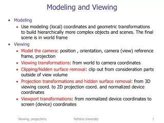
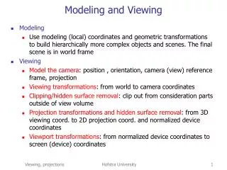
Modeling and Viewing . Modeling Use modeling (local) coordinates and geometric transformations to build hierarchically more complex objects and scenes. The final scene is in world frame Viewing Model the camera : position , orientation, camera (view) reference frame, projection

E N D
Modeling and Viewing • Modeling • Use modeling (local) coordinates and geometric transformations to build hierarchically more complex objects and scenes. The final scene is in world frame • Viewing • Model the camera: position , orientation, camera (view) reference frame, projection • Viewing transformations: from world to camera coordinates • Clipping/hidden surface removal: clip out from consideration parts outside of view volume • Projection transformations and hidden surface removal: from 3D viewing coord. to 2D projection coord. and normalized device coordinates • Viewport transformations: from normalized device coordinates to screen (device) coordinates Hofstra University
Viewing and Projection • Transforming • Modeling transformations (affine), 3D to 3D • Viewing transformations (affine), 3D to 3D • Linear in homogeneous coordinates • Images of parallel lines stay parallel • Transformation matrix in homogeneous coordinates has last row, 0 0 0 1 • Projection transformations (not affine), 3D to 2D • Linear in homogeneous coordinates • Images of parallel lines may intersect at infinity • Transformation matrix most general • Viewport transformations (affine), maps viewing window to viewport, 2D to 2D Hofstra University
Viewing Terminology • Viewing volume: the region in 3D that can contain objects that are visible by the camera • Projection: math transformations that maps from 3D to 2D (or 4D to 3D, in homogeneous) • Projection plane: the plain containing the 2D image • Viewing window: the rectangle in the image plane that will be mapped to the screen eventually • Viewport: 2D rectangle within the display window on the screen that shows the viewing window • Clipping: cutting off from consideration parts outside the view volume (done easier if the view volume is mapped to a canonical view volume which is a cube) Hofstra University
Graphics functions • Graphics systems support viewing by • Providing a viewing model whose parameters specify the camera • Providing functions for viewing, projection and viewport • Implementing viewing and projection transformations as matrix multiplications in homogeneous coordinates Hofstra University
Viewing APIs • The the position of the eye or camera is called the view reference point(VRP) • A unit view plane normal (VPN), is in the viewing direction, it is perpendicular to the image plane. In open GL VPN is in direction opposite to the one in which camera is looking • Another vector called the view-up vector is a vector specifying which is the approximate “up” direction for the camera Hofstra University
Camera Model: viewing VRP: Camera(eye) position, (u,v,n): camera frame. Viewing: specify VRP,n,VUP. Hofstra University
Viewing Coordinate System: (u,v,n) • right handed • v, the y-axis of the view frame, is the perpendicular projection of VUP on the projection plane • n is the z-axis of the view frame • u= v × n Hofstra University
Setting up the camera • Construct a scene and then look at it from a point of view, eye: • eye, the eyepoint, is the VRP specified in the world coordinates • Camera is pointed at a point at, the at point • These points determine VPN • vpn = eye – at Hofstra University
Two Points of View • Hold camera frame fixed, move objects in front of the camera • Model objects stationary and move the camera away from the objects Hofstra University
gluLookAt Utility Routine in OpenGL • Defines a viewing transformation matrix M, and M postmultiplies CTM, i.e. CTM=CTM*M • Eye point: eyex, eyey, andeyez. • At point: atx, aty,and atz. • VUP: upx, upy, and upz gluLookAt(eyex, eyey, eyez, atx, aty, atz, upx, upy, upz); Hofstra University
Viewing Transformations • Given 3D model of a scene/object in 4D homogeneous coordinates P, with respect to the world coordinate system • Given camera coordinate system (position, VRP, and camera frame (u,v,n) ) • Viewing transformation M converts coordinates of objects from world to camera coordinates • How? Hofstra University
Viewing Transformations • Let W=(O,ex,ey,ez) be the world coord. system • Let V=(VRP,u,v,n) be the camera coord. System • Let M be the change of frame matrix, mapping V to W, M = R.T(-VRP), where • T is a translation mapping VRP to O • R is a rotation aligning (u,v,n) with (ex,ey,ez), in 3D affine coordinates it represented by a matrix with rows u’,v’,n’ • Then for a point P with modeling coordinates w=(xw,yw,zw,1)’ the viewing coordinates are v =(vx,vy,vz,1)’, where Hofstra University
Custom Utility Routine • You might need to define your own transformation routine • Flight simulator: Display the world from the pilot’s point of view • Pilot see the world in terms of roll, pitch, and heading Hofstra University
Custom Utility Routine • The following routine could serve as the viewing transformation: • void pilotView{GLdouble planex, GLdouble planey, • GLdouble planez, Gldouble roll, • GLdouble pitch, GLdouble heading) • { • glRotated(roll, 0.0, 0.0, 1.0); • glRotated(pitch, 0.0, 1.0, 0.0); • glRotated(heading, 1.0, 0.0, 0.0); • glTranslated(-planex, -planey, -planez); • } Hofstra University
Custom Utility Routine • Orbiting the camera around an object that's centered at the origin • Use polar coordinates. • Let the distance variable define the radius of the orbit • The azimuth describes the angle of rotation of the camera about the object in the x-y plane • elevation is the angle of rotation of the camera in the y-z plane Hofstra University
Projections • Projecting: mapping from 3D viewing coordinates to 2D coordinates in projection plane. In homogeneous coordinates it is a map from 4D viewing coordinates to 3D. • Projections • Parallel: orthogonal and oblique • Perspective • Canonical views: orthographic and perspective projections Hofstra University
Perspective projection Projectors intersect at COP Hofstra University
Parallel Projections Projectors parallel. COP at infinity. Hofstra University
Parallel projections: summary • Center of projection is at infinity. • Projectors are parallel. • Parallel lines stay parallel • There is no forshorthening • Distances and angles are transformed consistently • Used most often in engineering design, CAD systems. Used for top and side drawings from which measurements could be made. Hofstra University
Orthographic Projection: projectors orthogonal to projection plane same for all points DOP (direction of projectors) Hofstra University
Orthographic Projections DOP is perpendicular to the view plane Hofstra University
Multiview Parallel Projection Faces are parallel to the projection plane Hofstra University
Isometric Projection Projector makes equal angles with all three principal axes All three axes are equally foreshortened Hofstra University
Mechanical Drawing isometric Hofstra University
Oblique Parallel Projections • Most general parallel views • Projectors make an arbitrary angle with the projection plane • Angles in planes parallel to the projection plane are preserved Hofstra University
Oblique Projections: projectors are not orthogonal to image plane Cavalier Angle between projectors and projection plane is 45°. Lines orthogonal to the projection plane Retain their exact length. Perpendicular faces are projected at full scale Cabinet Angle between projectors and projection plane is arctan(2)=63.4°. Lines orthogonal to the projection plane are projected at half length. Perpendicular faces are projected at 50% scale. Looks like forshorthening. Hofstra University
Perspective Projection • Most natural for people • In human vision, perspective projection of the world is created on the retina (back of the eye) • Used in CG for creating realistic images • Perspective projection images carry depth cues • Foreshorthening causes distant objects to appear smaller • Relative lengths and angles are not preserved • A perspective image cannot be used for metric measurements of the 3D world • Parallel lines not parallel to the image plane converge at a vanishing point • An axis (principal) vanishing point is a point of convergence for lines parallel to a principal axis of the object. We distinguish one-, two-, three-point projections.) Hofstra University
Vanishing Points Hofstra University
Vanishing Points Hofstra University
Early Perspective Giotto Not systematic—parallel lines do not converge to a single "vanishing" point Hofstra University
Math of Projections:Overview • Math of perspective projection, standard configuration • OpenGL perspective projections • Math of orthographic projection • OpenGL orthographic projections • Viewport transformations and setting them in OpenGL • Summary • Viewing transformations • Orthographic projection canonical viewing volume • Perspective projection canonical viewing volume • Hidden surface removal Hofstra University
Perspective Viewing Hofstra University
Perspective Projections -z -z Viewing direction orthogonal To projection plane Genaral perspective: Viewing direction is not orthogonal to projection plane Hofstra University
Perspective Projections • The graphics system applies a 4 x 4 projection matrix after the model-view matrix Hofstra University
Math of perspective projection • The discussion here is carried out with respect to the camera (view) reference frame, (VRP,u,v,n) • The projection transformation maps 3D points to 2D points in the projection plane • Standard configuration: • COP=VRP • Projection plane is orthogonal to z-axis, at z=d Hofstra University
Math of perspective projection • Standard configuration: • Let O be COP • Projection plane has equation z=d, d <0 • 3D point P has homogeneous coordinates (x,y,z,1) • It is mapped to point Q (xp,yp,d) in the projection plane • Q is on the segment PO, thus • Q=cP+(1-c)O, where 0<c<1 • Thus, xp = c.x, yp = c.y, d = c.z c = d/z • Thus, xp = (d/z).x, yp = (d/z).y , in affine coordinates • Note that projection is not linear in affine coordates. Hofstra University
Math of perspective projection • P=p(x,y,z,1) Q=q(d.x/z, d.y/z, d, 1), in homogeneous coordinates. • Perspective projection is not linear in affine coord. • Perspective projection is linear in homogeneous • From homogeneous to affine coordinates: (a,b,c,w) (a/w, b/w,c/w) • Thus (x,y,z,d/z) in homogeneous becomes (x/(z/d), y/(z/d),d,1) ==> (d.x/z, d.y/z,1) in proj. plane Hofstra University
Clipping • Object parts outside of the of the view volume are clipped • First we will discuss the openGL functions that set up the projection transformations • Next we will discuss the viewport transformation and setting the viewport in OpenGL • Last, we will go back to projection, and see how the graphics systems carry out efficiently the more general perspective projection by reducing it to the standard perspective, and then to the canonical orthographic • You can set up any projection you want (parallel or perspective) by setting up the the projection matrix directly • Although, more often we use affine transformations to reduce more general projections to the canonical ones Hofstra University
Perspective Viewing in OpenGL Depth of projection plane (size of clipping window) inside the pyramid does not matter. All that matters is object size relative to the window. The projection plane depth does not affect relative size. Thus in CG systems usually far or near plane is selected to be the projection plane. Near in openGL. Hofstra University
Projections in OpenGL frustum only fixed point Objects not in the view volume are clipped. View (projection) plane is front clipping plane. Hofstra University
OpenGL Perspective glFrustum(left, right, bottom, top, near, far); glMatrixMode(GL_PROJECTION); glLoadIdentity( ); glFrustum(left, right, bottom, top, near, far); The relationship between front(near) plane and COP(origin) define the steepness of the frustum Hofstra University
OpenGL Perspective gluPerspective(fovy, aspect, near, far); fov is the angle between the top and bottom planes Hofstra University
OpenGL Orthographic Projection glOrtho(left, right, bottom, top, near, far); Hofstra University
Standard Orthographic Projection Hofstra University
Viewport Transformation • viewport transformation corresponds to the stage where the size of the developed photograph is chosen • The viewport is measured in pixels, in screen window coordinates, which reflect the position of pixels on the screen relative to the lower left corner of the window • vertices outside the viewing volume have been clipped Hofstra University
Viewport Transformation • viewport is the rectangular region of the window where the image is drawn Hofstra University
Defining the Viewport • The window manager, not OpenGL, is responsible for opening a window on the screen • By default the viewport is set to the entire pixel rectangle of the window that's opened • Use the glViewport() command to choose a smaller drawing region void glViewport(GLint x, GLint y, GLsizei width, GLsizei height); size of viewport rectangle lower left corner Hofstra University
Defining The Viewport • By default, the initial viewport values are • (0, 0, winWidth, winHeight), • where winWidth and winHeight are the size of the window. • The aspect ratio of a viewport should generally equal the aspect ratio of the viewing volume • If the two ratios are different, the projected image will be distorted as it's mapped to the viewport Hofstra University
Viewport Distortion Hofstra University
Summary • World to View coordiantes • Camera position: VRP • Viewing transformation • Translate VRP to origin: T(-VRP) • Rotate, aligning view frame (u,v,n) with world frame • The composite transformation R.T will have the effect of transforming the coordinates of vertices from world to view coordinates Hofstra University