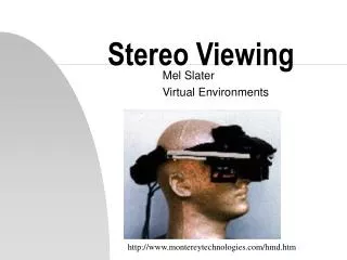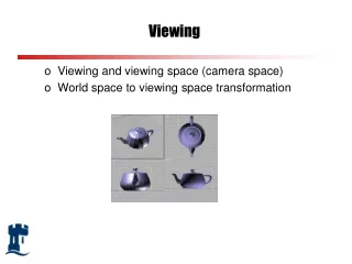
Viewing
Viewing. Open GL Lecture 11. Chapter 2 explained how to instruct OpenGL to draw the geometric models you want displayed in your scene. Now you must decide how you want to position the models in the scene, and you must choose a vantage point from which to view the scene.

Viewing
E N D
Presentation Transcript
Viewing Open GL Lecture 11
Chapter 2 explained how to instruct OpenGL to draw the geometric models you want displayed in your scene. • Now you must decide how you want to position the models in the scene, and you must choose a vantage point from which to view the scene. • You can use the default positioning and vantage point, but most likely you want to specify them Chaper 3 -- Viewing
This chapter explains how to use OpenGL to accomplish these tasks: • how to position and orient models in three-dimensional space • and how to establish the location -- also in three-dimensional space -- of the viewpoint. • A common mistake people make here is not thinking in three-dimensional space, they think in 2D space too soon. Chaper 3 -- Viewing
A series of three computer operations converts an object’s three-dimensional coordinates to pixel positions on the screen. • Transformations • represented by matrix multiplication • include rotation, translation, scaling, ... • Clipping • removing those objects (or parts of objects) that lie outside of the viewing window. • Viewport Transformation • establishing a correspondence between the coordinates and the screen pixels. Chaper 3 -- Viewing
Overview: The Camera Analogy • The process used to produce the desired scene for viewing is analogous to taking a photograph • Set up the tripod and point the cameras • viewing transformation • Arrange the scene to be photographed • model transformation • Choose the camera lens or adjust the zoom • projection transformation • Determine how large you want the photograph to be • viewport transformation Chaper 3 -- Viewing
A Simple Example: Drawing a Cube • Example 3-1 draws a cube that’s scaled by a modeling transformation. • The viewing transformation, gluLookAt( ), positions and aims the camera toward where the cube is drawn, • A projection transformation and viewport transformation are also specified. Chaper 3 -- Viewing
The Viewing Transformation • This is analogous to positioning and aiming the camera. • glLoadIdentity( ); • clears the current transformation matrix by loading it with the Identity Matrix. • gluLookAt(0.0,0.0,5.0, 0.0,0.0,0.0, 0.0,1.0,0.0 ); • The arguments indicate • where the camera is placed (0.0, 0.0, 5.0) • where it is aimed (0.0, 0.0, 0.0) • and which way is up. (0.0, 1.0, 0.0) • If this is not called, the default is the camera at the origin, looking out along the negative z-axis, with 0,1,0 as the up direction. Chaper 3 -- Viewing
The Modeling Transformation • You use the modeling transformation to position and orient the model. • you could rotate, translate, or scale the model (or some combination) • glScalef(1.0, 2.0, 1.0); • The arguments specify how the scaling should occur along the three axes. • if all are 1.0, it does nothing. • In this example, the cube is drawn twice as large int he y direction. Chaper 3 -- Viewing
The Projection Transformation • similar to choosing a lens for a camera. • In addition to the field of view considerations, the projection transformation determines how objects are projected onto the screen. • Two basic types of projections are provided by OpenGL • perspective • matches how you see things in daily life. • orthographic • maps objects directly onto the screen without affecting their relative sizes. Chaper 3 -- Viewing
glMatrixMode(GL_PROJECTION); • we are now working on the projection matrix. • later we call this with GL_MODELVIEW, so future changes affect the modleview matrix. • glLoadIdentity( ); • initializes the current projection matrix • glFrustrum(-1.0,1.0,-1.0,1.0,1.5,20.0); • defines the parameters of the projection transformation. • gluPerspective( ) could have been placed here instead. Chaper 3 -- Viewing
The Viewport Transformation • Together, the projection transformation and the viewport transformation determine how a scene gets mapped onto the computer screen. • The projection transformation specifies the mechanics of how the mapping should occur, and the viewport indicates the shape of the available screen area. • glViewport(0,0,w,h); • describes the origin within the window (0,0) • and the width and height of the available screen area. • This is typically called within reshape( ); Chaper 3 -- Viewing
Drawing the Scene • Once all the necessary transformations have been specified, you can draw the scene • (take the photograph) • As the scene is drawn, OpenGL transforms each vertex of every object in the scene by the modeling and viewing transformations. • Each vertex is then transformed as specified by the projection transformation and clipped • Finally the remaining transformed vertices are mapped onto the viewport. Chaper 3 -- Viewing
General-Purpose Transformation Commands • This section discusses some OpenGL commands that you might find useful as you specify desired transformations. • Command you have already seen: • void glMatrixMode(Glenum mode); • Specifies whether the modelview, projection, or texture matrix will be modified. • void glLoadIdnetity(void); • sets the currently modifiable matrix to the 4x4 identity matrix. Chaper 3 -- Viewing
New Commands: • void glLoadMatrix{fd}(const TYPE *m); • Sets the 16 values of the current matrix to those in the vector pointed to by m • void glMultMatrix{fd}(const TYPE *m); • multiplies the matrix specified by the 16 values in the vector pointed to by m • Note: the vectors described here as m have the elements from the matrix in column major order • Declare ma s a vector and remember this, not as a matrix because you will be doing it wrong… Chaper 3 -- Viewing
Viewing and Modeling Transformations • Viewing and modeling transformations are inextricably related in OpenGL • and are combined into a single modelview matrix. • One of the toughest problems newcomers to computer graphics face is understanding the effects of combined three-dimensional transformation. Chaper 3 -- Viewing
Thinking about Transformations • Start with a simple example, a 45 degree rotation, and a translation. • In general the order of transformations is critical. • If you do transformation A and then B, you almost always get something different than if you do them in the opposite order. Chaper 3 -- Viewing
Example: • If the goal is: • The code would look like this: • glMatrixMode(GL_MODELVIEW); • glLoadIdentity( ); • glMultMatrixf(N); • glMultMatrixf(M); • glMultMatrixf(L) • glBegin(GL_POINTS); • glVertex3f(p); // draws the transformed vertex • glEnd( ); Chaper 3 -- Viewing
Grand, Fixed Coordinate System • So, back to our example. If we want the box to be rotated and then translated to appear on the axis, we would do the Rotation first and then the Translation. • The formula would look like • The Code would look lie: • glMatrixMode(GL_MODELVIEW); • glLoadIdentity( ); • glMultMatrixf(T); • glMultMatrixf(R); • draw_the_object( ); Chaper 3 -- Viewing
Moving a Local Coordinate System • Another way to view matrix multiplications is to forget about the grand, fixed coordinate system in which your model is transformed and instead imagine that a local coordinate system is tied to the object you are drawing. • With this approach, the matrix operations appear in the natural order in the code • translate it down there. • rotate it in it’s coordinate system. • This is the approach you should use when applications such as articulated robot arms, so you can combine translation and rotation matrices as you go down the arm to figure out the placement of the fingers. Chaper 3 -- Viewing
Modeling Transformations • void glTranslate{fd}(TYPE x, TYPE y, TYPE z); • translates an object by the given x, y, and z values. • void glRotate{fd}(TYPE angle, TYPE x, TYPE y, TYPE z); • rotates counterclockwise (angle degrees) about a ray from the origin through the point (x,y,z) • void glScale{fd}(TYPE x, TYPE y, TYPE z); • stretches, shrinks, or reflects an object along the axes • In general you should limit your use of glScale to those cases where it is necessary, since using glScale decreases performance of lighting calculations Chaper 3 -- Viewing
Viewing Transformations • A viewing transformation changes the position and orientation of the viewpoint. • You can manufacture a viewing transformation in any of several ways • choose to use the default location and orientation. • Use one or more transformation commands • glTranslate*( ) • glRotate*( ) • Use the Utility Library routine glLookAt( ) • Create your own utility routine Chaper 3 -- Viewing
Projection Transformations • Before you issue any of the transformation commands described in this section, • glMatrixMode(GL_PROJECTION); • glLoadIdentity( ); • The purpose of the projection transformation is to define a viewing volume • it determines how an object is projected on the screen. • it defines which objects (or portions) are clipped. Chaper 3 -- Viewing
Perspective Projection • the farther an object is from the camera, the smaller it appears in the final image. • The viewing volume is a frustum • a truncated pyramid Chaper 3 -- Viewing
void glFrustum(Gldouble left, Gldouble right, Gldouble bottom, Gldouble top, Gldouble near, Gldouble far); • creates a matrix for a perspective-view frustum and multiplies the current matrix by it. • Although it is easy to understand conceptually, glFrustum( ) isn’t intuitive to use. • Instead you might want to try the Utility Library routine gluPerspective( ) • instead of specifying the corners of the near clipping place, you specify the angle of the field of view (q) in the y direction and the aspect ratio of width to height (x/y). You also specify the near clipping distance Chaper 3 -- Viewing
void gluPerspective(Gldouble fovy, Gldouble aspect, Gldouble near, Gldouble far); • creates a matrix for a symmetric perspective-view frustum and multiplies the current matrix by it. • You need to pick appropriate values for the field of view, or the image may look distorted. • A 94-degree field of view with a 35-millimeter camera requires a 20-millimeter lens (which is a very wide angle lens). Chaper 3 -- Viewing
Orthographic Projection • void glOrtho(Gldouble left, Gldouble right, Gldouble bottom, Gldouble top, Gldouble near, Gldouble far); Chaper 3 -- Viewing
Viewing Volume Clipping • After the vertices of the objects in the scene have been transformed by the modelview and projection matrices, any primitives that lie outside the viewing volume are clipped. • The six clipping planes are those that define the sides and ends of the viewing volume. • You can specify additional clipping planes and locate them wherever you choose. Chaper 3 -- Viewing
Viewport Transformation • Viewport Rectangle Chaper 3 -- Viewing
Defining the Viewport • The window system, not OpenGL, is responsible for opening a window on the screen. • by default the viewport is set to the entire pixel rectangle of the window that’s opened. • You use glViewport( ) to choose the drawing region. • void glViewport(Glint x, Glint y, Glsizei width, Glsizei height); • defines a pixel rectangle in the window to which the final image is mapped. Chaper 3 -- Viewing
Left figure shows a projection that maps a square image onto a square viewport using gluPerspective(fovy, 1.0, near, far) glViewport(0, 0, 400, 400) Chaper 3 -- Viewing
Right figure, the windows has been resize to a nonequilateral rectangular viewport, but the projection is unchangeed. The emage appears compressed along the x-axix. gluPerspective(fovy, 1.0, near, far) glViewport(0, 0, 400, 200) • To avoid the distortion , modify the espect ratio of the projection to match the viewport: gluPerspective(fovy, 2.0, near, far) glViewport(0, 0, 400, 200) Chaper 3 -- Viewing