Viewing
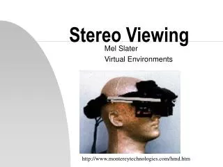
Viewing. Part II (The Synthetic Camera). Brownie camera courtesy of http ://www.geh.org/fm/brownie2/htmlsrc/mE13000034_ful.html. The camera and the scene. What does a camera do? Takes in a 3D scene

Viewing
E N D
Presentation Transcript
Viewing Part II (The Synthetic Camera) Brownie camera courtesy of http://www.geh.org/fm/brownie2/htmlsrc/mE13000034_ful.html 10/8/2013
The camera and the scene • What does a camera do? • Takes in a 3D scene • Places (i.e., projects) the scene onto a 2D medium such as a roll of film or a digital pixel array • The synthetic camera is a programmer’s model for specifying how a 3D scene is projected onto the screen Contour map courtesy of http://www.princeton.edu/~oa/manual/mapcompass.shtml 10/8/2013
3D Viewing: The Synthetic Camera • General synthetic camera: each package has its own but they are all (nearly) equivalent, with the following parameters/degrees of freedom (DoF) • Camera position • Orientation • Field of view (angle of view, e.g., wide, narrow/telephoto, normal...) • Depth of field/focal distance (near distance, far distance) • Tilt of view/ film plane (if not perpendicular to viewing direction, produces oblique projections) • Perspective of parallel projection (camera near objects or infinite distance away, resp.) • CS123 uses a simpler slightly less powerful model than the one used in the book • Omit tilt of view/film plane (i.e., no oblique projections), focal distance (blurring) 10/8/2013
Cameras in Rendering Process • We will detail coordinate systems for camera, i.e., view volume specification, projecting onto film plane, and transforming into viewport • Let’s first define viewport and view volume 10/8/2013
The pinhole model • Our camera is related to a pinhole. Looking through pinhole, see a volume of space. • Rays of light reflect off objects and converge to pinhole to let you see the scene on a film plane or wall behind the pinhole. The scene will be inverted. • The pinhole is where our camera position will be (“center of projection”), and the volume we see will be our “view volume” • In our camera, projectors intersect a plane, usually in between scene and pinhole, projecting the scene onto that plane • Lastly, in synthetic camera projection is mapped to some form of viewing medium (screen) Pinhole Camera Object Image Pinhole Synthetic Camera Object Pinhole Image 10/8/2013
Conical perspective view volume (eye’s is much wider, e.g., ≥180 degrees, esp. for motion!) eye Frustum: approximation to conical view volume synthetic camera View Volumes (focus of today’s lecture) • A view volume contains everything the camera sees • Conical – Approximates what eyes see, expensive math when clipping objects against cone’s surface (simultaneous linear and quadratics) • Can approximate this using a rectangular frustum view volume • Simultaneous linear equations for easy clipping of objects against sides (stay tuned for clipping lecture next time) • Also parallel view volumes, e.g., for orthographic projections. These don’t simulate eye or camera View volume (Parallel view) 10/8/2013
View Volumes and Projectors • Given our view volume, need to start thinking about how to project scene contained in volume to film plane • Projectors: Lines that essentially map points in scene to points on film plane • Parallel Volumes: Parallel Projectors, no matter how far away an object is, as long as it is in the view volume it will appear as same size, (using our simple camera model, these projectors are also parallel to look vector, the direction in which the camera is looking) • Perspective Volumes: Projectors emanate from eye point = center of projection, inverse of rays of light converging to your eye (see Dürer woodcut) Parallel volume projectors Perspective volume projectors 10/8/2013
The film plane • Film plane is a plane in world space – 3D scene is projected onto a rectangle (the film) on that plane using some projection transformation and from there onto the viewport on screen • Film for our camera model will be perpendicular to and centered around the camera’s look vector and will match dimensions of our view volume • Actual location of film plane along look vector doesn’t matter as long as it is between eye/COP and scene Look Vector Look Vector Film Plane Film Plane 10/8/2013
The viewport • Viewport is the rectangular area of screen where a scene is rendered • Corresponds to Window Manager’s client area • Note: window (aka Imaging Rectangle) in computer graphics means a 2D clip rectangle on a 2D world coordinate drawing, and viewport is a 2D integer coordinate region of screen space to which clipped window contents are mapped – it is the client area of a Window Manager’s window • Pixel coordinates for viewport are most commonly referred to using a (u,v) coordinate system • Unfortunately, that (u,v)nomenclature is also used for texture coordinates 10/8/2013
Up vector Look vector Constructing the view volume (1/2) • We need to know six parameters about our synthetic camera model in order to take a picture using our perspective view frustum • Position of camera (from where it’s looking) • Lookvector specifies direction camera is pointing • Camera’s Orientation is determined by Lookvector and angle by which the camera is rotated about that vector, i.e., the direction of Up vector in world coordinate system (WCS) Position 10/8/2013
Width angle Height angle Back clipping plane Front clipping plane Constructing the view volume (2/2) • Aspect ratio of the electronic “film:” ratio of width to height • Height angle: determines how much of the scene we will fit into our view volume; larger height angles fit more of the scene into the view volume (width angle determined by height angle and aspect ratio) • the greater the angle, the greater the amount of perspective distortion • Front and back clipping planes: limit extent of camera’s view by rendering (parts of) objects lying between them and throwing away everything outside of them – avoids problem of having far-away details map onto same pixel, i.e., sampling error (Optional) Focal length: objects at focal length are sharp, objects closer/farther are blurry 10/8/2013
1) Position (1/1) • Where is the camera located with respect to the origin, in the world coordinate system? • For our camera in 3D space we use a right-handed coordinate system • Open your right hand, align your palm and thumb with the +x axis, point index finger up along the +y axis, and point your middle finger towards the +z axis • If you’re looking at a screen, the z axis will be positive coming towards you Courtesy of http://viz.aset.psu.edu/gho/sem_notes/3d_fundamentals/gifs/left_right_hand.gif 10/8/2013
y x Up vector -z point to look at (x’, y’, z’) Look vector z 2 & 3) Orientation: Look and Up vectors (1/2) • Orientation is specified by a direction to look in (equivalently, a point in 3D space to look at) and a vector defining the rotation of the camera about this direction • These correspond to the Look vector and Up vector • Note: gluLookAt()takes nine values: the xyz-coordinates of the point to look at, the coordinates of the location of the camera, and the components of the Upvector (recall we used gluLookAt()in lab03!) • In diagram below, camera is positioned at origin, but that isn’t typical camera Position 10/8/2013
Look vector Position 2 & 3) Orientation: Look and Up vectors (2/2) Projection of Up vector • Look Vector • Direction the camera is pointing • Three degrees of freedom; can be any vector in 3-space • Up Vector • Determines how camera is rotated about Look vector • For example, holding camera in portrait or landscape mode • Up vector must not be co-linear to Look vector but it doesn’t have to be perpendicular either – actual orientation will be defined by the unit vector v perpendicular to Look in the plane defined by Look and Up Up vector Any of v, v1, v2, v3could be the Up vector 10/8/2013
The camera coordinate space (1/2) • The equivalent of x, y and z axes in camera space are unit vectors u, v and w (not to be confused with homogenous coordinate, w) • Also a right handed coordinate system • w is a unit vector in the opposite direction of the look vector (i.e. the look vector lies along the –w axis) • v is the part of the up vector perpendicular to the look vector, normalized to unit length • u is the unit vector perpendicular to both v and w 10/8/2013
The camera coordinate space (2/2) • There are three common transformations that use the camera space axes • Roll: • Rotating your camera around w • Yaw: • Rotating your camera around v • Pitch • Rotating your camera around u • To perform rotations about camera’s axes, send camera to origin and rotate to align its axes with the world coordinate axes, then use our rotation matrices to perform these transformations, un-rotate, and un-translate 10/8/2013 Roll, Yaw, Pitch image courtesy of http://3.bp.blogspot.com/_dbbuwCxZzCE/TQuhLBALxJI/AAAAAAAAAAo/oV8D5B4YijQ/s1600/pry.png
Aside: The camera as a model • There are different ways we can model a camera • In the generalized model we have a camera and a scene where both the camera and objects in the scene are free to be transformed independently • In a more restricted model we have a camera that remains fixed in one position and orientation • To “transform the camera” we actually apply inverse transformation to objects in scene • This is the model OpenGL uses; note however that GLU abstracts this concept away from the programmer (gluLookAt()) Field of view in OpenGL can be thought of as the view from the camera looking down –z axis at the origin Object moves to left to simulate a camera moving to right Translate “camera” to the right 10/8/2013
1:1 Courtesy of http://www3.flickr.com/photos/zerogrizzly/4037144257/ 4) Aspect Ratio (1/1) Courtesy of http://en.wikipedia.org/wiki/File:Aspect_ratio_4_3_example.jpg • Analogous to dimensions of film in camera • Ratio of width to height of viewing window • Viewport’s aspect ratio usually defined by device being used • Square viewing window has a ratio of 1:1 • NTSC TV is 4:3, HDTV is 16:9 or 16:10 • Aspect ratio of viewing window defines dimensions of the image that gets projected to film plane, after which it is mapped to viewport • Typically it’s a good idea to have same aspect ratio for both your viewing window and viewport, to avoid distortions/stretching • Note: the black strips on the 16:9 image is a technique called letter boxing. It preserves the aspect ratio of the image when the screen can’t accommodate it. This is in contrast to simply stretching the image which distorts the images (most notably, faces) 4:3 Courtesy of http://forum.videohelp.com/threads/236536-720-vs-704 16:9 10/8/2013
Width angle Height angle 5) View Angle (1/2) • Determines amount of perspective distortion in picture, from none (parallel projection) to a lot (wide-angle lens) • In a frustum, two viewing angles: width and height angles • Usually width angle is specified using height angle and aspect ratio • Choosingview angle is analogous to photographer choosing a specific type of lens (e.g., a wide-angle or telephoto lens) 10/8/2013
5) Viewing Angle (2/2) • Lenses made for distance shots often have a nearly parallel viewing angle and cause little perspective distortion, though they foreshorten depth • Wide-angle lenses cause a lot of perspective distortion Resulting picture 10/8/2013
6) Near and Far Clipping Planes (1/3) • With what we have so far we can define four rays extending to infinity. These define the edges of our current view volume • Now we need to bound front and back to make a finite volume – can do this using the near and far clipping planes, defined by distances along look vector (also note that our look vector and clipping planes are perpendicular) • This volume (the frustum) defines what we can see in the scene • Objects outside are discarded • Objects intersecting faces of the volume are “clipped” 10/8/2013
6) Near and Far Clipping Planes (2/3) • Reasons forfront (near) clipping plane: • Usually don’t want to draw things too close to camera • would block view of rest of scene • objects would be distorted • Don’t want to draw things behind camera • wouldn’t expect to see things behind camera • in the case of perspective camera, if we were to draw things behind camera, they would appear upside-down and inside-out because of perspective transformation 10/8/2013
6) Near and Far Clipping Planes (3/3) • Reasons for back (far) clipping plane: • Don’t want to draw objects too far away from camera • distant objects may appear too small to be visually significant, but still take long time to render • by discarding them we lose a small amount of detail but reclaim a lot of rendering time • can also help to declutter a scene • These planes need to be properly placed, not too close to the camera, not too far (mathematical justification later) 10/8/2013
Games and Clipping Planes (1/2) • Sometimes in a game you can position the camera in the right spot that the front of an object gets clipped, letting you see inside of it. • Video games use various techniques to avoid this glitch. One technique is to have objects that are very close to the near clip plane fade out before they get cut off, as can be seen below • This technique gives a clean look while solving the near clipping problem (the wooden fence fades out as the camera gets too close to it, allowing you to see the wolf behind it). Fence is partially transparent Fence is opaque Screenshots from the game, Okami 10/8/2013
Games and Clipping Planes (2/2) • Ever played a video game and all of a sudden some object pops up in the background (e.g., a tree in a racing game)? That’s object coming inside farclip plane. • Old solution: add fog in the distance. A classic example, Turok: Dinosaur Hunter • Modern solution (e.g. Stone Giant), dynamic level of detail: mesh detail increases when closer • Thanks to fast hardware and level of detail algorithms, we can push the far plane back now and fog is much less prevalent Courtesy of http://www.atomicgamer.com/screenshots/game-1552/10965-800.jpg Courtesy of http://images.tweaktown.com/news/1/4/14981_07.jpg 10/8/2013
Focal Length • Some camera models take afocal length • Focal Length is a measure of ideal focusing range; approximates behavior of real camera lens • Objects at distance equal tofocal length from camera are rendered in focus; objects closer or farther away thanfocal length get blurred • Focal length used in conjunction with clipping planes • Only objects within view volume are rendered, whether blurred or not. Objects outside of view volume still get discarded Courtesy of http://3d-pic.3ddl.net/uploads/allimg/110617/13-11061G05J20-L.jpg 10/8/2013
The Parallel View Volume (1/2) • Up until now we’ve been describing the specifications for a perspective view volume • We also need to discuss the parallel view volume (as mentioned last time, used for orthogonal/metric views) • What do we need to know this time? • Everything we wanted for a perspective view volume except for width and height angles, replaced by just a width and height (also the width and height of our film on our film plane) • A parallel view volume is a parallelepiped (all opposite edges parallel) Rectangular parallelepiped 10/8/2013
Width Far distance Height Look vector Near distance Projection of up vector Up vector Position The Parallel View Volume (2/2) • Objects appear the same size no matter how far away they are since projectors are all parallel • A benefit of parallel view volume is that it’s really easy to project a 3D scene to a 2D medium 10/8/2013
Capabilities of the Generalized Camera (1/2) • In a more generalized camera the viewing window doesn’t have to be centered about the Location+LookDirection • Nor does it have to be perpendicular to the LookDirection (d) • This allows us to use a more flexible view as well as enable the use of more view types • Using an uncentered film we can essentially choose which part of our original perspective projection to view 10/8/2013
Capabilities of the Generalized Camera (2/2) • Using a parallel view volume we can do oblique projections (cavalier, cabinet, perspective oblique) where the look vector/projectors and film plane aren’t perpendicular: • Our model of a camera is not all-encompassing • There are some capabilities that we have omitted for the sake of simplicity • Our film is centered around the camera position and always perpendicular to the look vector Non-oblique view volume: Oblique view volume: Look vector is perpendicular to film plane Look vector is at an angle to the film plane 10/8/2013
Next Task… • We have now seen how to construct a perspective and parallel view volume and we mentioned how a scene is projected in these volumes onto the film plane • But these view volumes can be located anywhere and positioned in any way depending on how our camera is specified • How can we transition from knowing what the view volume looks like to actually rendering an image to the screen • Next, describe canonical view volume and how we can use it for rendering • P.S.: Get ready to use our linear algebra transformations! 10/8/2013