Viewing
Viewing. Doug James’ CG Slides, Rich Riesenfeld’s CG Slides, Shirley, Fundamentals of Computer Graphics, Chap 7. Wen-Chieh (Steve) Lin Institute of Multimedia Engineering. Getting Geometry on the Screen. Given geometry in the world coordinate system, how do we get it to the display?

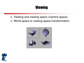
Viewing
E N D
Presentation Transcript
Viewing Doug James’ CG Slides, Rich Riesenfeld’s CG Slides, Shirley, Fundamentals of Computer Graphics, Chap 7 Wen-Chieh (Steve) Lin Institute of Multimedia Engineering
Getting Geometry on the Screen Given geometry in the world coordinate system, how do we get it to the display? • Transform to camera coordinate system • Transform (warp) into canonical view volume • Clip • Project to display coordinates • Rasterize ILE5014 Computer Graphics 10F
Vertex Transformation Pipeline ILE5014 Computer Graphics 10F
Vertex Transformation Pipeline glMatrixMode(GL_MODELVIEW) glMatrixMode(GL_PROJECTION) glViewport(…) ILE5014 Computer Graphics 10F
OpenGL Transformation Overview glMatrixMode(GL_MODELVIEW) gluLookAt(…) glMatrixMode(GL_PROJECTION) glFrustrum(…) gluPerspective(…) glOrtho(…) glViewport(x,y,width,height) ILE5014 Computer Graphics 10F
Viewing and Projection • Our eyes collapse 3-D world to 2-D retinal image (brain then has to reconstruct 3D) • In CG, this process occurs by projection • Projection has two parts: • Viewing transformations: camera position and direction • Perspective/orthographic transformation: reduces 3-D to 2-D • Use homogeneous transformations ILE5014 Computer Graphics 10F
Pinhole Optics F P • Stand at point P, and look through the hole—anything within the cone is visible, and nothing else is • Reduce the hole to a point - the cone becomes a ray • Pin hole is the focal point, eye point or center of projection ILE5014 Computer Graphics 10F
Perspective Projection of a Point Image W F I World • View planeorimage plane- a plane behind the pinhole on which the image is formed • sees anything on the line (ray) through the pinhole F • a point W projects along the ray through F to appear at I (intersection of WF with image plane) ILE5014 Computer Graphics 10F
Image Formation Image W Image F I F World World • Projecting a shape • project each point onto the image plane • lines are projected by projecting end points only Camera lens Note: Since we don't want the image to be inverted, from now on we'll put F behind the image plane. ILE5014 Computer Graphics 10F
Orthographic Projection World Image F • When the focal point is at infinity the rays are parallel and orthogonal to the image plane • When xy-plane is the image plane (x,y,z) -> (x,y,0) front orthographic view ILE5014 Computer Graphics 10F
Multiview Orthographic Projection • Good model for CAD and architecture. No perspective effects. front side top ILE5014 Computer Graphics 10F
Assume view transformation is done • Let’s start with a simple case where the camera is put at the origin, and looks along the negative z-axis! • Simple “canonical” views: orthographic projection perspective projection ILE5014 Computer Graphics 10F
Orthographic Viewing Cube • (l,b,n) = (left, bottom, near) • (r,t,f) = (right, top, far) ILE5014 Computer Graphics 10F
Orthographic Projection • Map orthographic viewing cube to the canonical view volume • 3D window transformation • [l, r] x [b, t] x [f, n] [-1, 1]x[-1, 1]x[-1,1] ILE5014 Computer Graphics 10F
Orthographic Projection (cont.) • 3D window transform (last class) • [l, r] x [b, t] x [f, n] [-1, 1]x[-1, 1]x[-1,1] • zcanonical is ignored ILE5014 Computer Graphics 10F
Map Image Plane to Screen y (1,1) x x (nx, ny) (-1,-1) y Screen Image Plane ILE5014 Computer Graphics 10F
Map Image Plane to Screen • If y-axis of screen coord. points downward • [-1,1] x [-1, 1] [-0.5, nx-0.5] x [ny-0.5, -0.5] translation scale reflection ILE5014 Computer Graphics 10F
Orthographic Projection Matrix • Put everything together ILE5014 Computer Graphics 10F
Arbitrary Viewing Position • What if we want the camera somewhere other than the canonical location? • Alternative #1: derive a general projection matrix. (hard) • Alternative #2: transform the world so that the camera is in canonical position and orientation (much simpler) ILE5014 Computer Graphics 10F
Camera Control Values • All we need is a single translation and angle-axis rotation (orientation), but... • Good animation requires good camera control--we need better control knobs • Translation knob - move to the lookfrom point • Orientation can be specified in several ways: • specify camera rotations • specify a lookat point (solve for camera rotations) ILE5014 Computer Graphics 10F
A Popular View Specification Approach • Focal length, image size/shape and clipping planes are in the perspective transformation • In addition: • lookfrom: where the focal point (camera) is • lookat: the world point to be centered in the image • Also specify camera orientation about the lookfrom-lookfat axis ILE5014 Computer Graphics 10F
Implementing lookat/lookfrom/vup viewing scheme • Translate by lookfrom, bring focal point to origin • Rotate lookfrom - lookat to the z-axis with matrix R: • w = (lookfrom-lookat) (normalized) and z = [0,0,1] • rotation axis: a = (w × z)/|w × z| • rotation angle: cosθ = w•z and sinθ = |w × z| • Rotate about z-axis to get vup parallel to the y-axis ILE5014 Computer Graphics 10F
It's not so complicated… y x vup y z x y lookfrom x z START HERE z w Translate LOOKFROM to the origin Rotate the view vector (lookfrom - lookat) onto the z-axis. y x Multiply by the projection matrix and everything will be in the canonical camera position z Rotate about z to bring vup to y-axis ILE5014 Computer Graphics 10F
Translate Camera Frame • Let e=(ex, ey, ez) be the “lookfrom” position y x vup y z x lookfrom z START HERE w Translate LOOKFROM to the origin ILE5014 Computer Graphics 10F
Rotate Camera Frame • You can derive these two rotation matrices based on what you learned in the last class y x y x z z Translate LOOKFROM to the origin Rotate the view vector (lookat -lookfrom) onto the z-axis. y x z Rotate about z to bring vup to y-axis ILE5014 Computer Graphics 10F
Rotate Camera Frame (cont.) • Alternatively, we can view these two rotations as a single rotation that aligns u-v-w-axes to x-y-z-axes! v y x z w w: lookat – lookfrom v: view up direction u = v x w ILE5014 Computer Graphics 10F
Recall Global vs. Local Coordinate… • x, y, u, v, o, e are all vectors in global system In global coord. (xp,yp) In local coord. (up,vp) ILE5014 Computer Graphics 10F
Think about 3D case …. • Given two coordinate frames, how do you represent a vector specified in one frame in the other frame? ? w v u Z P e Y ? X ILE5014 Computer Graphics 10F
Viewing Transformation • Put translation and rotation together w v Z u P Y e local coordinate world coordinate X ILE5014 Computer Graphics 10F
Orthographic Projection Summary Given 3D geometry (a set of points a) • Compute view transformation Mv • Compute orthographic projection Mo • Compute M = MoMv • For each point ai, compute p = Mai ILE5014 Computer Graphics 10F
A Simple Perspective Camera • Canonical case: • camera looks along the z-axis (toward negative z-axis) • focal point is the origin • image plane is parallel to the xy-plane at distance d • We call d the focal length, mainly for historical reasons Image plane Center of projection ILE5014 Computer Graphics 10F
Geometry Eq. for Perspective Projection view plane y ys g e d z • Diagram shows y-coordinate, x-coordinate is similar • Point (x,y,z) projects to e: eye position g: gaze direction ILE5014 Computer Graphics 10F
Perspective Projection Matrix • Projection using homogeneous coordinates: • transform (x,y,z) to • 2-D image point: • discard third coordinate • apply viewport transformation to obtain physical pixel coordinates Divide by 4th coordinate (the “w” coordinate) ILE5014 Computer Graphics 10F
View Volume • Pyramid in space defined by focal point and window in the image plane (assume window mapped to viewport) • Defines visible region of space • Pyramid edges are clipping planes ILE5014 Computer Graphics 10F
View Frustum • Truncated pyramid with near and far clipping planes • Why far plane? Allows z to be scaled to a limited fixed-point value (z-buffering) • Why near plane? Prevent points behind the camera being seen ILE5014 Computer Graphics 10F
Why Canonical View Volume? • Rather than derive a different projection matrix for each type of projection, we can convert all projections to orthogonal projections with the default view volume • This strategy allows us to use standard transformations in the pipeline and makes for efficient clipping ILE5014 Computer Graphics 10F
Taking Clipping into Account • After the view transformation, a simple projection and viewport transformation can generate screen coordinate. • However, projecting all vertices are usually unnecessary. • Clipping with 3D volume. • Associating projection with clipping and view volume normalization. ILE5014 Computer Graphics 10F
Normalizing the Viewing Frustum • Solution: transform frustum to a cube before clipping • Converts perspective frustum to orthographic frustum • This is yet another homogeneous transform! ILE5014 Computer Graphics 10F
Map Perspective View Volume to Orthographic View Volume • We already know how to map orthographic view volume to canonical view volume • Set view plane at the near plane ILE5014 Computer Graphics 10F
Map Perspective View Volume to Orthographic View Volume • Map [x,y,n] to [x, y, n] • Map [xf/n,yf/n,f] to [x, y, f] ILE5014 Computer Graphics 10F
Projection Matrix is not unique • Mp is not unique ILE5014 Computer Graphics 10F
Properties of Perspective Transform • Lines and planes are preserved • Parallel lines (not parallel to the projection plan) won’t be parallel after transform • vanishing point: parallel lines intersect at the vanishing point vanishing point ILE5014 Computer Graphics 10F
Orthographic Projection Summary Given 3D geometry (a set of points a) • Compute view transformation Mv • Compute orthographic projection Mo • Compute M = MoMv • For each point ai, compute p = Mai ILE5014 Computer Graphics 10F
Perspective Projection Summary Given 3D geometry (a set of points a) • Compute view transformation Mv • Map perspective to orthographic Mp • Compute orthographic projection Mo • Compute M = MoMpMv • For each point ai, compute p = Mai ILE5014 Computer Graphics 10F