Exploring Viewing Transformations in Computer Graphics
Understand how to transform 3D world to 2D surface for graphics display devices, Camera Analogy, OpenGL’s 'look at' point, Viewing and Projection transformations explained.

Exploring Viewing Transformations in Computer Graphics
E N D
Presentation Transcript
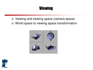
Viewing • Viewing and viewing space (camera space) • World space to viewing space transformation
world coordinates VIEWINGTRANSFORMATION viewing coordinates World to Viewing Coordinates • Graphics display devices are 2D rectangular screens. Hence we need to understand how to transform our 3D world to a 2D surface • Viewing the desired scene is analogous to taking pictures using a camera • We now need to
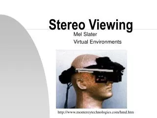
Camera Analogy • View is described in terms of: • camera position in world coordinate system • camera direction (viewing direction) • camera orientation: usually defined by the up vector • aperture size: field of view
yW P0 N xW V zW yW P0 yW P0 N xW xW zW zW View Coordinate System • specify a view reference point in the world coordinate system. This can be any point along the camera direction, or the camera position itself • specify the view plane normal N - this gives the camera, or Z direction • specify the view-up direction, V - this gives the camera up direction, or Y direction v’ v n v=v’-(v.n) n
V U P0 N Viewing Coordinate System • We can construct a vector U perpendicular to both V and N, and this will correspond to the Xv axis. How? • We can define U as right, V as up, and N as towards the viewer: a right handed system UV=N • We can also define U as right, V as up and N as into the scene: a left handed system VU=N, in which bigger N values mean points are further away • OpenGL is right handed yW xW zW
yW P0 Q xW zW View Coordinate System • Some systems (e.g., OpenGL) allow you to specify a ‘look at’ point, Q, from which N is calculated as the direction to the ‘look at’ point from the view reference point
World to Viewing • Objects must be viewed in the viewing space • This can be done by aligning the view coordinate system with world coordinate system, e.g., view reference point is transformed to world origin, and U, V, N are aligned with X, Y, Z directions through rotations y (x0, y0, z0) x z
V Ux Uy Uz 1 U (Ux, Uy, Uz,1)T = P0 N y x z World to Viewing • Translate view origin to world origin, then align U, V and N axes with X, Y and Z directions by rotation R = Rz. Ry. Rx • rotate around X to bring N into the X-Z plane • rotate around Y to align N with Z • rotate around Z to align V with Y • An easier way to work out the rotation matrix R: • U in world space should be (1,0,0) in view space • V should be (0,1,0) • N should be (0,0,1) • So we have the following equations 1. R*(Ux, Uy, Uz,1)T = (1,0,0,1) 2. R*(Vx, Vy, Vz,1)T = (0,1,0,1) 3. R*(Nx, Ny, Nz,1)T = (0,0,1,1)
World to Viewing Transformation • Remember U.U=1, U.V=0, U.N=0, V.N=0, so if we choose the rotation matrix as • The equations 1,2,3 will be satisfied • The rotation matrix is a “change of basis” matrix • So viewing transformation from world space to viewing space is: M = RT R =
y Pw=(1,1,0) v x u n (0,0,1) z What’s Pw in viewing coordinates? Intuitively, P in viewing coordinate is (-1,1,1), but how do we derive it? 1. Translate view origin to world origin with translation vector (0, 0, -1) 2. Multiply Pw by matrix M below to align viewing axes with world axes -1 0 0 0 M = 0 1 0 0 0 0 -1 1 So Pw in viewing space is: Pv = M T Pw u, v, n in world space: u=(-1,0,0) v=(0,1,0) n=(0,0,-1)
yv xv zv OpenGL Viewing Coordinate System • The default camera is placed at the coordinate origin of world space (U aligned with the X axis, V aligned with Y, and N aligned with Z), looking along the negative z-direction, and the view plane is perpendicular to the viewing direction
Projection • We need to transform from a special viewing coordinate system (camera on z-axis pointing along the axis) into a projection coordinate system viewing coordinates projection coordinates PROJECTIONTRANSFORMATION
P1 P2 P2 view plane Parallel Projection - Two types • In parallel projection, the observer position is at an infinite distance, so the projection lines are parallel • Orthographic parallel projection has view plane perpendicular to direction of projection • Oblique parallel projection has view plane at an oblique angle to direction of projection
yv xv zv Parallel Projection Calculation looking along x-axis P (x,y,z) (xp,yp,d) yV viewing space d o - zV view plane yP = y Similarly, xP = x
Parallel Projection Calculation • So • x = xp • y = yp • z = d • The projection transformation matrix is simply If view plane is xoy plane, Then d=0 x y z 1 xp yp d 1 • 1 0 0 0 • 0 1 0 0 • 0 0 d/z 0 • 0 0 0 1 = projection space projection matrix viewing space
P1 P1’ camera P2 P2’ view plane Perspective Projection • In a perspective projection, object positions are projected onto the view plane along lines which converge at the observer, or Centre of Projection (COP) • Perspective projection gives realistic views, but does not preserve proportions - projections of distant objects are smaller than projections of objects of the same size which are closer to the view plane (fore-shortening)