Download
1 / 27
270 likes | 386 Vues
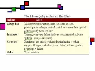
Learn about the categories and features of electromagnetic phenomena, such as transients and voltage variations, crucial to the power system community. Explore types like impulsive and oscillatory transients, short and long duration voltage variations, voltage imbalance, and waveform distortion.

E N D
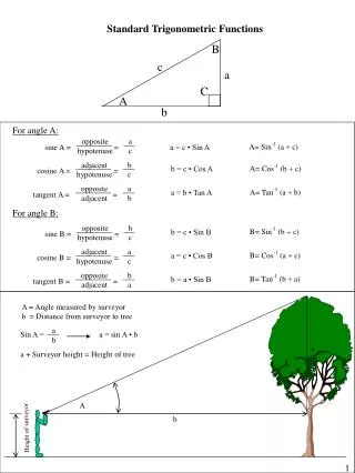
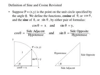
Refer to the categories and characteristic of power system electromagnetic phenomena (for the PQ community) A. Transients: Undesirable momentary deviation of the supply voltage or load current. Also known as surges or spikes. 2 categories of transients: impulsive and oscillatory Impulsive transients: a sudden, non-power frequency change in the steady-state condition of voltage, current or both, that is unidirectional in polarity (either +ve or –ve). Oscillatory transients: same definition as impulsive but the only different is bidirectional in polarity (includes both +ve or –ve values). High-frequency oscillatory transient- greater than 500kHz Medium-frequency oscillatory transient – between 5kHz to 500kHz Low-frequency oscillatory transient – less than 5kHz.
Impulsive transient Oscillatory transient
B. Short duration voltage variation: Interruption, sag and swell. Each type can be designated as instantaneous(0.01-0.5 sec), momentary (0.5-3 sec) or temporary (3-60 sec) Interruption - a reduction in the supply voltage, or load current, to a level less than 0.1 p.u for a time less than 1 minute. It can caused by system faults, system equipment failures or control and protection malfunctions. interruption
i) Voltage sag (dip) Decrease to between 0.1 to 0.9 p.u. in rms voltage at the power frequency for durations from 0.5 cycles(8ms) to 1 minute. Also called voltage dips. Caused by faults, increased load demand and transitional events such as large motor starting. Voltage sag
ii) Voltage swell An increase in rms voltage in the range of 1.1 to 1.8 p.u. for duration from 0.5 cycles (8ms) to 1 minute. Also called momentary overvoltage. Caused by system faults, load switching and capacitor switching. Instantaneous voltage swell caused by a SLG fault.
C . Long duration voltage variations: Voltage deviation longer than 1 min. 3 types: Overvoltage - An increase in the rms ac voltage greater than 110% at power frequency for duration more than 1 minute Undervoltage - A decrease in rms ac voltage to less than 90% at power frequency for duration more than 1 minute Sustained interruption - When voltage is 0 for duration more than 1 minute.
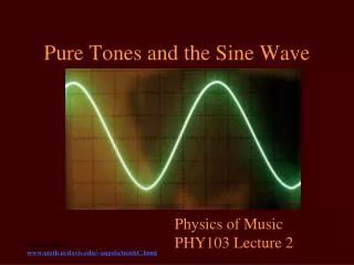
D. Voltage imbalance Deviation of each phase from the average voltage of all three phases. Most equipment can tolerate voltage imbalance of 2%. Can cause network problems such as mal-operation of protection relays and voltage regulation equipment, and also overheat of motor and transformer. E. Waveform distortion Steady-state deviation from an ideal sine wave of power frequency. 5 primary types of waveform distortion: DC offset, harmonics, inter-harmonics, notching and noise.
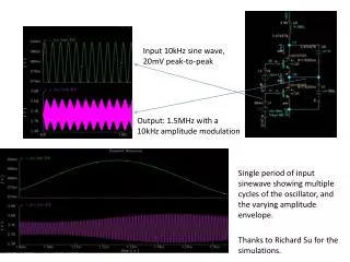
i) DC offset Presence of a dc voltage or current in an AC system. Can result in corrosion of network and customer’s earthing system. ii) Harmonics Periodic sinusoidal distortions of the supply voltage or load current caused by non-linear loads. Harmonics are measured in integral multiples of the fundamental supply frequency, 50Hz (i.e. 150Hz is third harmonic) Harmonic current caused by nonlinear loads like adjustable speed drive, SMPS in computer, power electronic devices and medical test equipment. Effect: overheating of txt, cable and motor; relay trip and incorrect measurement of V and I by meters.
Creation of nonlinear waveform by adding fundamental and third harmonic frequency waveform Nonlinear load waveform and harmonic content
Harmonic distortion.. • Distortion factor (THD): • Ratio of rms voltage or current harmonic content of a periodic wave to the rms of fundamental content of the wave, expressed as a percent. Also known as total harmonic distortion (THD). • % THD = • where : I1,rms is the fundamental sinusoidal input current and Irms is the input utility rms current (may not be sinusoidal, depends on load)
Harmonic distortion.. • Displacement power factor (DPF): • Ratio between active power (W) to apparent power (VA) of the fundamental wave. DPF is same as PF in linear circuit with sinusoidal V and I. DPF is cosine of displacement angle between V and I waveform. • DPF = cos Φ
Power factor (PF): Ratio of total active power to total apparent power of composite wave including all harmonic components.
Harmonic Standards There are few standards that generally practiced by international communities such as in US and European countries, that imposed on the power electronic equipment which is connected to the utility system. a) IEC 61000-3-2 - Having four classifications as A, B, C, and D classes depending on the nature of the individual equipment. b) IEEE 519-1992 - More related to the power or utility provider on the distribution or feeder side as Point of Common Coupling (PCC).
a) IEC 61000-3-2 i) Class A : Balanced three-phase equipment and all other equipment that not stated in the following classes. ii) Class B : Portable tools such as hand tools and lawnmowers. iii) Class C : Lighting equipment and including dimming devices. iv) Class D : Equipment having an input current with a “ special waveshape ” and active input power from 75W to 600W. Examples are personal computers, monitors, UPS and others that normally having AC to DC rectifiers or Switching Mode Power Supplies (SMPS).
IEC 61000-3-2 Class D harmonics and current limits. where n is the odd-ordered harmonic number.
b) IEEE 519-1992 Utility Interface
Reference book : Power Electronics : Converter, Applications, And Design – Mohan, Undeland, Robin. Chapter 18.
iii) Inter-harmonics Caused by waveforms that have frequency components that are not integral multiples of the fundamental frequency, 50Hz. The effects of inter-harmonics are light flicker, audible noise in tv sets, radios and audio equipment, and vibration in rotating induction machines. iv) Notching It is a periodic voltage disturbance caused by normal operation of power electronic devices when current is commutated from one phase to another (two phases of supply are effectively short-circuited for a short time).
v) Electrical Noise Caused by a low voltage, high frequency (but lower than 200Hz) signal superimposed on 50Hz fundamental waveform. Cause: HV lines, start up of large motor, radio and TV station, SMPS, fluorescent light and power electronic devices. Notching
Fundamental sine wave Noise Electrical noise adds “hash” or mess onto the fundamental sine wave
vi) Voltage fluctuation Rapid changes in voltage within the allowable limits of the nominal voltage, e.g. 0.9 to 1.1 p.u. Cause lamps to blink rapidly, often referred to as “flicker” and is visible to human eyes at flickering frequencies of 6-8Hz. Use static VAR controller (SVCs) to control voltage fluctuation frequency by controlling amount of reactive power supplied to the equipment (i.e. arc furnaces). vii) Power frequency variation Deviation of power system fundamental frequency from its nominal value (50Hz or 60Hz).