Download
1 / 35
390 likes | 673 Vues
10.1 Magnetic Flux & Induced Currents 10.2 Induced EMF: Faraday’s Law 10.3 Direction of EMF: Lenz’s Law. http://web.ncf.ca/ch865/graphics/MagnetAndCoil.jpeg. Michael Faraday was aware of the magnetic effect of a current and he

E N D
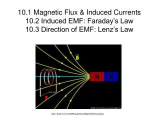
10.1 Magnetic Flux & Induced Currents 10.2 Induced EMF: Faraday’s Law 10.3 Direction of EMF: Lenz’s Law http://web.ncf.ca/ch865/graphics/MagnetAndCoil.jpeg
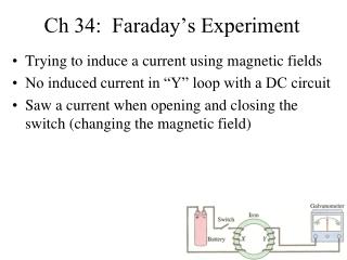
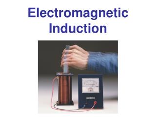
Michael Faraday was aware of the magnetic effect of a current and he spent six years searching for the reverse effect — that is, the electrical effect of magnetism. His equipment consisted of two coils of insulated wire, wrapped around a wooden ring. One coil was connected to a battery, the other to a GALVANOMETER, a sensitive current detector. Faraday observed that the galvanometer needle gave a little kick when the battery switch was closed and a little kick the opposite way when the switch was opened. The rest of the time, either with the switch open or closed, the needle was stationary, reading zero. The current was momentary, not the constant current he was looking for. What Faraday had observed came to be called ELECTROMAGNETIC INDUCTION.
SAC ALERT! AUGUST 4 SAC: Electric Power Summary of Practical Activities Today’s experiment: Electromagnetic Induction. Mutual Induction Apparatus: Experiment 1: Induction From A Magnet Experiment 2: Induction From Another Coil
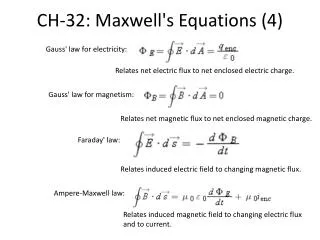
To describe the ‘amount of field’ more precisely, physicists use a quantity called MAGNETIC FLUX(ΦB), measured in Webers (1 W = 1 Tm2).
Where the lines are crowded the field is strong; where they are less dense the field is weaker. Magnetic flux then, is rather like the total number of these This picture leads to the common expression for the strength of the magnetic field, B, as the MAGNETIC FLUX DENSITY.
Faraday went on to show that the amount of induced current in a coil was proportional to the rate at which the number of lines of force cutting through a coil was changing; that is, the rate of change of magnetic flux passing through the coil. Faraday also realised that the induced current depended on the particular characteristics of the coil as well as the flux changes. He found that it was the EMF (or voltage) induced that was independent of the particular characteristics of the circuit. The reason for this is not hard to see if we remember that charges moving in a magnetic field experience a force.
The right-hand rule tells us that the force on positive charges in the wire in Figure 10.5 would be in the direction along the wire and out of the page. The force on the negative electrons in the wire will be inwards. Thus the closer end of the wire (to us) will become positive, and the other end, into the page, will become negative (charge separation). This will result in a potential difference (ΔV) created across the ends of the wire. The potential difference is equal to the potential energy gained per unit of charge.
The relationship E = vBl is only useful for a straight wire moving in a magnetic field. However, it can be used to derive a more generally useful expression if we note that, as the wire moves, it sweeps across lines of magnetic flux.
Consider the loop shown above. The magnet is moving to the left and increasing the amount of flux in the loop. Clearly a current will be induced in the loop, but in which direction? Imagine that the induced current is clockwise. Use of the right-hand grip rule will show that this current will produce a magnetic flux that points in the same direction as that from the magnet. Now this would create an interesting situation! The flux from the induced current would add to the increasing flux from the magnet and produce a greater change of flux. This in turn would increase the induced current, which would increase the flux change, which would further increase the induced current—and so on. In other words, we have an impossible situation.
Lenz realised that the flux created by the induced current must be such as to oppose the change of flux from the magnet. If we imagine the reverse of the previous situation—that is an induced current that flows anticlockwise around the loop—we can see that the flux created by the induced current does oppose the increasing flux from the magnet.
As the magnet approaches the loop, the applied B field in the centre increases.This is a change. An Induced Field is created which attempts to negate the applied field - ie to keep the total field at zero - its original value.
SAC ALERT! Today’s experiment: Lenz’s Law.
SAC ALERT! Today’s experiment: Another Demonstration of Lenz’s Law. From: https://webapps.lsa.umich.edu/physics/demolab/Content/FeaturedDemos.aspx?id=pira&pid=5
Drop a coin through the metal (non-magnetic) tube. The coin will fall through, as you might expect. It accelerates very close to the acceleration due to gravity. From http://regentsprep.org/Regents/physics/phys08/clenslaw/default.htm
Drop a magnet through the tube. You will notice that the magnet falls very slowly. This is because the copper tube "sees" a changing magnetic field from the falling magnet. This changing magnetic field induces a current in the copper tube.
The induced current in the copper tube creates its own magnetic field that opposes the magnetic field that created it.