Download
1 / 41
410 likes | 559 Vues
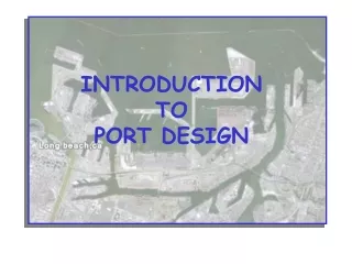
INTRODUCTION TO PORT DESIGN. Importance of Ports to Alaska. Port – Definition. A location for transfer of cargo between ships and shore. A port normally includes docks, uplands and infrastructure necessary for commercial activity. Small Boat Harbor - Definition.

E N D
Port – Definition • A location for transfer of cargo between ships and shore. • A port normally includes docks, uplands and infrastructure necessary for commercial activity.
Small Boat Harbor - Definition • A location for permanent or temporary moorage of small unattended vessels. • Moorings normally consist of floating docks protected by a breakwater. • Vessel size in small boat harbors generally vary from about 18 foot skiffs up to about 150 foot commercial fishing boats.
Example Port – Anchorage, Ak. One mile
Anchorage Example Port Long Beach, Ca. 1 mile
Port Characteristics • Normally Accommodates vessels ranging from about 150 feet to over 900 feet. • Dock structures are generally fixed (not floating) and vessels are attended at all times. (Note: Areas of high tidal ranges require constant attention to mooring lines or use self tensioning winches). • Port Design includes Dock structures, uplands, and associated infrastructure. • May or may not include a protective Breakwater.
PIER • Good for Access to Deep Water • Vessels Can Be Moored on Two or More Sides • Limited Weight Capacity (pile supported) • Limited Working Space • Commonly Used for Fuel Transfer & Light Cargo
WHARF • Moorage Parallel to Shore. Docking on Only One Side • More Robust Than Piers. Good for Heavy Duty Transfer of Cargo – (E.G. Containers) • Normally Constructed Close to Shore Where Depths Increase Rapidly
Design ConsiderationsPhysical Site Conditions • Winds • Waves • Currents • Ice • Sedimentation • Soils (foundations) • Water Depths • Available Uplands • Access • Environmental Impacts • Other
Design Considerations Structural • Size and displacement tonnage (weight) of ship . . . is there tug assist? • What is the impact energy (fendering) • What are the wind and current loads? • Selection of materials (steel, concrete, wood?) • Other
Six Degrees of Boat Motion(3 rotation and 3 translation) Surge Pitch Heave Roll Yaw Sway
ENVIRONMENTALDock Design & Fish Migration Pile supported docks are normally preferred for fish migration; however there may be concern for shading There is concern that vertical faced docks force juvenile salmon into deep water. Sometimes this can be mitigated by hanging material from dock face.
ENVIRONMENTALDock design & Fish migration dock Causeway Breach beach beach
Vertical Datum • MHW (Nautical Chart Uplands) • NGVD (Highways ?) • MSL (Airports ?) • MLLW (Harbors, Marine and Nautical Chart Soundings) Always Show Datum on Plan Sheets
Primary concern for port operations Distribution of Ocean Wave Energy Residual Ocean Swell – about 10 to 15 seconds Most Inland Waters about 4 to 6 second design wave 84 SPM
What tools can we use to describe it numerically ?? Typical Sea State
Typical Wave Record (Time Series) Use Fast Fourier Transform (FFT) to get Frequency Spectra Typical Sea State – How It’s Quantified “Similar to earthquake design for Bridges”
We Develop a Numerical Time Series Representing a design Storm Event In Design we go backwards Starting with a Spectral Model (Usually JONSWAP or SMB)
Note roughly 5 day cycle of storm events March 8 Storm in Gulf
Local Fetches Seward
O Wind Stress Factor (UA ) O Fetch (F) O Water Depth (d) Estimating Wave Height & Period Wave Height (H) Wave Period (T)
Shallow Water Wave Transformation • Refraction • Diffraction • Shoaling • Reflection
The End The end
Small Boat Harbors • A location for permanent or temporary moorage of small unattended vessels. • Moorings normally consist of floating docks. • The vessel size in harbors generally vary from about 18 foot skiffs up to about 150 foot commercial fishing boats. • Larger boats are more often associated with ports and movement of cargo.
Linear Wave Theory L=5.12 T^2 Fig. 2-6 84 SPM
Meteorology https://www.fnmoc.navy.mil/PUBLIC/WAM/all_npac.html
Requires Iterative Solution Common Equations for Port and Harbor Design Wave Length (Deep Water): When depth(d) > L/2 Deep or Lo= 5.12 T 2 (feet) Wave Length : When depth(d) < L/2 However: Shallow