Download

1 / 25
250 likes | 383 Vues
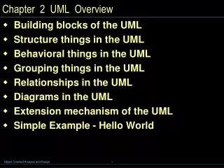
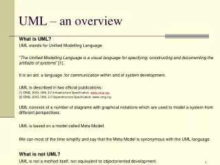
An Overview of UML. The Unified Modeling Language. UML is a graphical language used by software engineers to model software systems during development. UML provides for several different kinds of diagrams that represent different views and different levels of detail.

E N D
The Unified Modeling Language • UML is a graphical language used by software engineers to model software systems during development. • UML provides for several different kinds of diagrams that represent different views and different levels of detail. • UML is a synthesis of software methodologies developed earlier by Booch, Rumbaugh, and Jacobson among others. • Now an industry standard maintained by the Object Management Group (www.omg.org).
Software Methodology • Programmers have always drawn pictures to describe software. • Flow charts. • Data structure diagrams. • Dataflow diagrams. • Database diagrams. • The methodology wars. • 1970s – 1980s
Software Methodology • By 1990 there were a number of successful methodologies. • Gurus • Books • CASE tools • Seminars • Many common concepts but different notations, details.
Software Methodology • Everyone recognized the need for a standard. • Everyone wanted it to be their methodology. • Rational and the three amigos – 1995 • Grady Booch • Jim Rumbaugh • Ivar Jacobson • “Unified” their previously separate methodologies • The Object Management Group (OMG) – 1996 • RFP for a standard OO modeling notation
The OMG and UML • Several companies responded to the OMG RFP. • Proposals coalesced into a single proposal – The UML • UML Version 1 adopted as a standard – 1997 • Widely accepted and used over the next five years. • Updated by Versions 1.1 – 1.5. • Many books based on Version 1.4 • Version 2.0 approved 2004 • Standards bloat?
Diagrams in UML UML diagrams are used to describe: • Real things in the real world. • Physical things: cars, airplanes, buildings • Abstract things: • insurance policy, organization structure, eyeglass prescription, class schedule • Software constructs. • Classes corresponding to real world things. • Classes with visible behavior. • Purely internal classes.
Ways of Using UML • UML as a sketch • UML as a blueprint • UML as a programming language
Diagrams in UML • UML 1.4 defines nine kinds of diagrams • Structural Diagrams (four kinds) • Behavioral, or Dynamic, Diagrams (five kinds) • Will not use all of them. • UML 2.0 defines 13 kinds • Generally don’t need to worry about differences between UML 1.4 and UML 2.0.
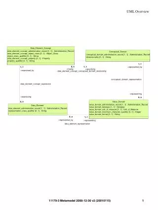
Structural Diagrams • Class Diagrams • The “things” that make up the system • Their attributes, operations, associations • Class vs. Object Diagrams • Implementation Diagrams • Deployment Diagrams • Where systems components will be installed • How they interact • Component Diagrams • Dependencies among system components
Behavioral Diagrams • External: Use Case Diagrams • Describe externally visible behavior • Interactions between the system and the outside world • Internal • Activity Diagram • Similar to a flow chart • Sequence Diagram • Time Line • Communication Diagram • Another view of interactions over time • State Machine Diagram • States, Events, Actions
From Object-Oriented Software Engineering using UML, Patterns, and Java, Second Edition, by Bernd Bruegge and Allen H. Dutoit Prentice Hall/Pearson, 2004 Use Case Diagramsrepresent the functionality of the system
Class Diagrams Describe the structure of the system “Is A” Relationships From The Unified Modeling Language User Guide, by Booch, Jacobson, and Rumbaugh, Addison Wesley, 1999
Composition and Aggregation: “Has A” Relationships From The Unified Modeling Language User Guide, by Booch, Jacobson, and Rumbaugh, Addison Wesley, 1999 Class Diagrams Class Associations
Activity Diagrams • A form of flow chart. • Typically applies to a particular use case. • Shows the order in which things happen. • Which activities can take place concurrently. • Which activities cannot start until somthing else is completed.
Activity Diagrams From The Unified Modeling Language User Guide, by Booch, Jacobson, and Rumbaugh, Addison Wesley, 1999
Interaction Diagrams • Used to formalize the dynamic behavior of the system and to visualize the communication among objects. • UML provides two kinds of diagrams to show interactions among actors and objects: • Sequence diagrams • Communication diagrams (UML 2.x) • Called Collaboration diagrams in UML 1.x • Not used in some texts
Sequence Diagrams • Show interactions among actors and objects • In terms of messages sent from one to another • With a common time axis in the vertical dimension. • The word "messages" is used in an abstract sense. • Information flow • No implications about how implemented.
From Object-Oriented Software Engineering using UML, Patterns, and Java, Second Edition, by Bernd Bruegge and Allen H. Dutoit Prentice Hall/Pearson, 2004 Sequence Diagrams
Communication Diagrams Show interactions among objects or roles in terms of messages sent along links representing associations. From UML Distilled(Third Edition), by Martin Fowler, page 132.
State Machine Diagrams • Called “Statechart” diagrams in UML 1.x. • Describe the behavior of the an object in terms of a number of states and transitions between them. • Important when the response of the system to a given stimulus depends on what has happened previously.
State Machine Diagrams • Elements of a State Machine Diagram: • States • Determine what the system does in response to a given stimulus. • Reflect the effects of past history on system behavior • Events (External stimuli) • Cause actions • Cause transitions between states • Actions • While in a state • On state transition
State Machine Diagrams Initial State Final State From Object-Oriented Software Engineering using UML, Patterns, and Java, Second Edition, by Bernd Bruegge and Allen H. Dutoit Prentice Hall/Pearson, 2004
State Machine Diagrams What does a SimpleWatch do when button1 is pressed while the watch is in the BlinkSeconds state?
Assignment • google UML • Check out web sites. • Find tutorials and references. End of Presentation