Download

1 / 36
360 likes | 458 Vues
Discover the key concepts of Unified Modeling Language (UML) in this session, including modeling methodologies, language syntax, system structuring, and visualization using UML diagrams. Learn how UML is utilized for database and software modeling, and explore the 4+1 view for conceptualizing system functionalities. Gain insights into the different UML diagrams available, such as class, object, use case, and activity diagrams. Dive deeper into the structural, behavioral, grouping, and annotational aspects of UML.

E N D
Topics covered in this Session 1. Introducing UML. 2. What constitutes the UML. 3. Concepts of UML.
Modeling • Modeling is a way of thinking about the problems using models organized around the real world ideas. • A modeling method comprises a language and also a procedure for using the language to construct models. • modeling is the only way to visualize your design and check it against requirements before your crew starts to code. Refernces http://www.omg.org/gettingstarted/what_is_uml.htmhttp://www.inconcept.com/JCM/April1998/halpin.html
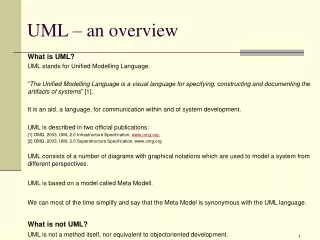
Introduction What is UML? • Is a language. It is not simply a notation for drawing diagrams, but a complete language for capturing knowledge(semantics) about a subject and expressing knowledge(syntax) regarding the subject for the purpose of communication. • Applies to modeling and systems. Modeling involves a focus on understanding a subject (system) and capturing and being able to communicated in this knowledge. • It is the result of unifying the information systems and technology industry’s best engineering practices (principals, techniques, methods and tools). Refernces www.sqae.com/UML.ppt
Unified Modeling Language (UML) • used for both database and software modeling • version 1.1 was adopted in November 1997 by the Object Management Group (OMG) as a standard language for object-oriented analysis and design • Initially based on a combination of the Booch, OMT (Object Modeling Technique) and OOSE (Object-Oriented Software Engineering) methods, UML was refined and extended by a consortium of several companies, and is undergoing minor revisions by the OMG Revision Task Force. • Ivar Jacobson is known as the father of Use Cases. Refernces http://www.inconcept.com/JCM/April1998/halpin.html
The Unified Modeling Language. Unification Specify Construct The UML Goal Visualize Document Programming Language Tools / Repository Specification Process
UML Concepts-The 4+1 view • Use Case view • Understandability • Logical View • Functionality • Process View • Performance • Scalable • Throughput • Implementation View • Software management • Deployment View • System topology • Delivery • Installation
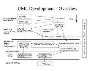
UML Diagrams UML includes diagrams for • use cases • static structures (class and object diagrams) • behavior (state-chart, activity, sequence and collaboration diagrams) • implementation (component and deployment diagrams). For data modeling purposes UML uses class diagrams, to which constraints in a textual language may be added
The UML process There are four kinds of things in the UML. 1. Structural Things. 2. Behavioral Things. 3. Grouping Things. 4. Annotational Things.
Things in UML Structural Things Behavioral Things Grouping Things Annotational Things 1. Notes 1. Class 1. Interaction 1. Packages 2. Interface 2. State Mechanism 3. Collaboration 4. Use Case 5. Active Class 6. Components 7. Nodes
Diagrams in UML A Diagram is the graphical presentation of a set of elements, most often rendered as a connected graph of things and relationships. UML includes 9 such diagrams. 1. Class Diagram. 2. Object Diagram. 3. Use Case Diagram. 4. Sequence Diagram. 5. Collaboration Diagram. 6. State Chart Diagram. 7. Activity Diagram. 9. Deployment Diagram.
Use case diagrams • Use Case Diagrams • Use Case Diagrams describe the functionality of a system and users of the system. These diagrams contain the following elements: • Actors, which represent users of a system, including human users and other systems. • Use Cases, which represent functionality or services provided by a system to users.
High Level Use Case Diagram Manage Resources Resource Manager Manage Projects Project Manager System Admin System Administrator
Managing Resources Use Case Diagram Add Skill Remove Skill Find Skill Update Skill Resource Manager Add Resource Find Resource Remove Resource Update Resource Unassign Skill from Resource Assign Skill from Resource
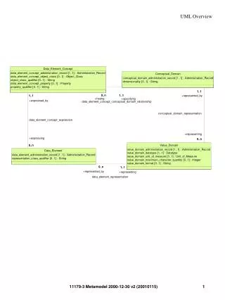
Class Diagrams • Class Diagrams describe the static structure of a system, or how it is structured rather than how it behaves. These diagrams contain the following elements. • Classes, which represent entities with common characteristics or features. These features include attributes, operations and associations. • Associations, which represent relationships that relate two or more other classes where the relationships have common characteristics or features. These attributes and operations.
High-Level Resource Class Diagram Skill Resource-Skill Resources Salaried Hourly
Detailed Resource Class Diagram Skill Name: String Desc: String Create(): Skill setName(): (Name:String) getName(): String setDesc(): (Desc:String) getDesc(): String destroy() Resource Skill Resource Hourly Salaried
Object Diagrams • Object Diagrams describe the static structure of a system at a particular time. Whereas a class model describes all possible situations, an object model describes a particular situation. Object diagrams contain the following elements: • Objects, which represent particular entities. These are instances of classes. • Links, which represent particular relationships between objects. These are instances of associations. • .
Sequence Diagrams • Sequence Diagrams describe interactions among classes. These interactions are modeled as exchange of messages. These diagrams focus on classes and the messages they exchange to accomplish some desired behavior. Sequence diagrams are a type of interaction diagrams. Sequence diagrams contain the following elements: • Class roles, which represent roles that objects may play within the interaction. • Lifelines, which represent the existence of an object over a period of time. • Activations, which represent the time during which an object is performing an operation. • Messages, which represent communication between objects.
Collaboration Diagrams • Collaboration Diagrams describe interactions among classes and associations. These interactions are modeled as exchanges of messages between classes through their associations. Collaboration diagrams are a type of interaction diagram. Collaboration diagrams contain the following elements. • Class roles, which represent roles that objects may play within the interaction. • Associationroles, which represent roles that links may play within the interaction. • Message flows, which represent messages sent between objects via links. Links transport or implement the delivery of the message.
Statechart Diagrams • Statechart (or state) diagrams describe the states and responses of a class. Statechart diagrams describe the behavior of a class in response to external stimuli. These diagrams contain the following elements: • States, which represent the situations during the life of an object in which it satisfies some condition, performs some activity, or waits for some occurrence. • Transitions, which represent relationships between the different states of an object.
Activity Diagrams • Activity diagrams describe the activities of a class. These diagrams are similar to statechart diagrams and use similar conventions, but activity diagrams describe the behavior of a class in response to internal processing rather than external events as in statechart diagram. • Swimlanes, which represent responsibilities of one or more objects for actions within an overall activity; that is, they divide the activity states into groups and assign these groups to objects that must perform the activities. • Action States, which represent atomic, or noninterruptible, actions of entities or steps in the execution of an algorithm. • Action flows, which represent relationships between the different action states of an entity.
Activity Diagrams (Cont...) • Object flows, which represent the utilization of objects by action states and the influence of action states on objects.
Component Diagrams Component diagrams describe the organization of and dependencies among software implementation components. These diagrams contain components, which represent distributable physical units, including source code, object code, and executable code.
Deployment Diagrams Deployment diagrams describe the configuration of processing resource elements and the mapping of software implementation components onto them. These diagrams contain components and nodes, which represent processing or computational resources, including computers, printers, etc.
Advantages of UML • You can model just about any type of application, running on any type and combination of hardware, operating system, programming language, and network, in UML. • Used for modeling middleware • Built upon the MOF™ metamodel for OO modeling • UML Profiles (that is, subsets of UML tailored for specific purposes) help you model Transactional, Real-time, and Fault-Tolerant systems in a natural way. Refernces http://www.omg.org/gettingstarted/what_is_uml.htm
Advantages of UML • UML is effective for modeling large, complex software systems • It is simple to learn for most developers, but provides advanced features for expert analysts, designers and architects • It can specify systems in an implementation-independent manner • 10-20% of the constructs are used 80-90% of the time • Structural modeling specifies a skeleton that can be refined and extended with additional structure and behavior • Use case modeling specifies the functional requirements of system in an object-oriented manner
Other uses of UML • analyze existing source code and reverse-engineer it into a set of UML diagrams. • execute UML models, typically in one of two ways: • execute your model interpretively in a way that lets you confirm that it really does what you want, but without the scalability and speed that you'll need in your deployed application. • work only within a restricted application domain generate program language code from UML, producing most of a bug-free, deployable application that runs quickly if the code generator incorporates best-practice scalable patterns for, • A number of tools on the market generate Test and Verification Suites from UML models. Refernces http://www.omg.org/gettingstarted/what_is_uml.htm
OMG’s Model Driven architecture ™ (MDA™) Based firmly on OMG standards, MDA aims to separate business or application logic from underlying platform technology. UML forms the foundation of MDA and can be used for PIMs and PSMs. Refernces http://www.omg.org/mda/