3.3 Multi-Layer V i+1 H i Channel Routing
260 likes | 508 Vues
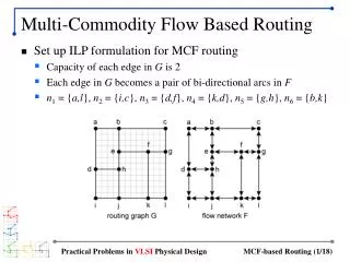
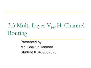
3.3 Multi-Layer V i+1 H i Channel Routing. Presented by Md. Shaifur Rahman Student # 0409052028. Vertical Layer (Top). Layer 1. Horizontal Layer. Layer 2. Layer 3. Via Connection. Vertical Layer (Bottom). Multi-Layer 3D View. 3-Layer VHV Channel Router.

3.3 Multi-Layer V i+1 H i Channel Routing
E N D
Presentation Transcript
3.3 Multi-Layer Vi+1Hi Channel Routing Presented by Md. Shaifur Rahman Student # 0409052028
Vertical Layer (Top) Layer 1 Horizontal Layer Layer 2 Layer 3 Via Connection Vertical Layer (Bottom) Multi-Layer 3D View 3-Layer VHV Channel Router
When 2-layer model has no solution! • If Vertical Constraint Graph (VCG) has a cycle, there is no feasible solution under 2 layer no-dogleg Manhattan routing model 1 2 2 1
Necessity of more than 2 layers! Vertical Constraint Graph with a Cycle 1 2
Solution in VHV Routing • Any Vertical Constraint (ni, nj) can be resolved by routing vertical wire segments of ni and nj in two separate vertical layers on either side of horizontal layer • We never have more than two net terminals in a single column • Hence, only horizontal constraint remains in VHV model • Therefore the novel algorithms MCC1 or MCC2 can be used in VHV model
Routing Channels Top View VHV Routing Scenario 1 2 2 1
1 2 2 Routing Channels in 3D VHV Routing Channels 1
Channel Density dmax • Local Density of a column is the maximum number of nets passing through the column • Channel Density of a channel is the maximum of all local densities • A channel with density dmax has at least one column spanned by dmax nets
Channel Density dmax(Contd.) Channel Density 5 1 2 3 4 5
Multiple Horizontal Layers • Multiple Horizontal Layers can reduce routing area • If there are i horizontal layers H1, H2,.., Hi, and channel density is dmax, then minimum number of track required per horizontal layer is :
Multiple Horizontal Layers (Contd.) dmax nets in a column must be distributed in i horizontal layers.
What does Vi+1Hi mean? • Total number of vertical layers is one more than total number of horizontal layers • Each horizontal layer is sandwiched between 2 vertical layers Vertical Layer Horizontal Layer 4 Vertical Layers and 3 Horizontal Layers, Channel Density 4
Benefit of Vi+1Hi Novel MCC1 and MCC2 algorithms can be applied (like 2-layer model) to Vi+1Hi model without introduction of new constraints
Application of MCC1 / MCC2 in Multilayer Channel Routing Problem • Compute Minimum Clique Cover for Horizontal Non-constraint Graph (HNCG) • There are dmax cliques of the minimum clique cover. Assign dmax cliques arbitrarily to i horizontal layers. Maximum number of tracks per horizontal layer is
Illustration of MCC1/MCC2 Applied to Multilayer CRP 1 Clique Cover CC={C1, C2,C3, C4}whereC1: {5, 1, 4}C2: {2, 7}C3: {3}C4: {6} 2 7 3 6 4 5
Illustration of MCC1/MCC2 Applied to Multilayer CRP (Contd.) Place nets of same clique in the same track in any horizontal layer I5 I1 I4 I2 I7 I3 I6 5 3 6 2 1 7 4
Application of MCC1 / MCC2 in Multilayer Channel Routing Vertical Wire Layout • Suppose that two nets ng and nh that are members of two separate cliques Cp and Cq respectively, are laid out in the same horizontal layer Hr • Suppose has ng terminal on the top and nh has terminal at the bottom • Then there are two possible cases • Case 1: Cp is assigned to the track above that of Cp • Case 2: Cp is assigned to the track below that of Cp
Vertical Wire Layout : Case 1 In this case both the vertical wire segments are assigned to the same vertical layer Vr just below the horizontal layer Hr Hr ng nh Vr
Vertical Wire Layout : Case 2 Hr In this case, vertical wire segments of ng and nh are assigned to vertical layers Vr and Vr+1 respectively (above and below the horizontal layer Hr ) ng Vr+1 nh Vr
Application of MCC1 / MCC2 in Multilayer Channel Routing (Contd.) • In this manner, all vertical constraints in a channel are resolved • The result is a (2i+1)-layer Vi+1Hi routing solution using tracks
If there is a column spanned by no nets! For example leftmost column has terminal 0 spanned by no other net I5 I1 I4 I2 I7 I3 I6 0 5 3 6 2 1 7 4
The result is increase in running time of MCC1 0 • Running time of MCC1 is O(n+e) where n is the number of nets and e is the size of HNCG • If HNCG is sparse e = O(n) • But for introduction of node ‘0’, e = O(n2) • Thus, if there is a column spanned by no other net, running time of MCC1 becomes O(n+O(n2)) = O(n2) 1 2 7 3 6 4 5
Preprocessing of MCC1 • We can split the net list at each such un-spanned column • For example the net list {4,2,1,3,0,6,7,5} should be split into {4,2,1,3} and {6,7,5} • MCC1 should be run independently on each of the splits • Since HNCG for each split is now sparse i.e. has size O(n), MCC1 now runs in O(n)
MCC2 performs better than MCC1 • Runs in O(nlogn) time • Is independent of size of HNCG
Any Question Please ? Thank You