Image Quality Radiographic Resolution.
Image Quality Radiographic Resolution. Demelza Green Jan 2004 Technologies for Imaging. Radiographic Resolution. The resolving power of a radiograph. How close structures can be and still appear separate - fine detail. Radiographic Resolution.

Image Quality Radiographic Resolution.
E N D
Presentation Transcript
Image QualityRadiographic Resolution. Demelza Green Jan 2004 Technologies for Imaging.
Radiographic Resolution • The resolving power of a radiograph. • How close structures can be and still appear separate - fine detail.
Radiographic Resolution • Expressed as a measurement of line pairs per mm (lp/mm) • the number of line pairs resolved within a mm determines the quality of the recording medium. • A line pair is made of a line and a space. • Human eye is limited to resolve 5 lp/mm. • Radiographic film 10 lp/mm
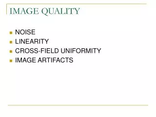
Noise • Noise - contributes no useful diagnostic information and serves only to detract from the quality from the image.
Noise • Quantum mottle = image noise. • Fluctuation in the quantity of photons that contribute to the image formation. • Image appear mottled or blotchy. • Result of fast screens that require less exposure - less photons. • Decreases image detail.
Unsharpness • Three Types • Geometric. • Movement. • Photographic.
Unsharpness • SOD - source object distance • SID - source image (receptor) distance • OID - object image (receptor) distance
Geometric Unsharpness (Ug) • Size of focal spot. • Image magnification - • Geometric unsharpness = • Poor film/screen contact. SID SOD Focal spot size x OID SOD
Movement unsharpness (Um) • Exposure time. • Subject motion - voluntary and involuntary. • Immobilisation.
Photographic Unsharpness (Up) • Screen and film crystal size • Duplitised screens/ emulsions (crossover) • Reflective screen layers.
Unsharpness • Total unsharpness • = √ Ug2 + U m2+Up2
Contrast • What is contrast? • The capacity of showing different densities • The whiteness of the bone against the blackness of the film and the range of greys in between.
Radiographic Contrast • Subject ContrastFilm/Receptor Contrast • KVp Film Type • Tissue composition Direct exposure/ intensifying screens • Contrast Medium Processing Conditions
Contrast • High Contrast film • Black/white • CXR for bony mets or rib fractures. • Low Contrast film • Shades of grey • CXR for lung lesions or chest infections.
Radiographic Contrast • Tissue Composition. • Composition and thickness of tissue affect absorption. • create a range of densities (contrast) • anatomical structures with a wide range of tissue composition will produce high subject contrast. • Those with a similar range produce low subject contrast
Radiographic Contrast • Contrast media • for imaging areas of low subject contrast. • Positive contrast agents e.g. barium have high atomic no. and absorb more x-rays than the surrounding structures. • Negative contrast agents e.g. air have low atomic no. produce more density than surrounding structures.
Scatter. • when the x-rays transverse the body tissues either are absorbed or scattered or transmitted without interactions • scattered photons reaching the detector form a ‘fog’ on the radiographic which blurs the image and obscures the anatomical details degradation of the image
Scatter • scattered photons can be absorbed by the body tissues increase in patient’s dose • minimise the scattered radiation generated in the body tissues. • minimise the scattered radiation reaching the detector.
Contrast • Kilovoltage. • Low KVp decreased penetration • more absorption • more density differences - high contrast
Contrast • Kilovoltage • High KVp increased penetration. • less absorption. • less density differences - low contrast. • Increase in scatter - unwanted interactions with film.
Scatter Radiation • Using the minimum field size (collimation); the larger the irradiated volume the higher the scatter generated in the body; minimise the irradiated volume by correct collimation
Digital Imaging • Define spatial resolution. • Describe factors influencing spatial resolution. • Fully describe the concept of windowing. • Define the terms window width and window level.
Spatial resolution • Matrix size - greater the matrix then smaller the pixel size improved spatial detail. • As with conventional radiography detail lost during imaging process e.g. on the plate.
Digital Resolution • Typical TV monitor 2.5 lp/mm • Radiographic Film 10 lp/mm • need a tv monitor martix of at least 2048x2048 - fine line monitors - expensive. • Resolution poor.
Windowing There are 2000 levels of grey. Human eye cannot detect between small level changes. Windowing is a contrast enhancing technique. Allows us to pick a section within that scale and assign grey levels depending on what we are looking at. + 1000 Grey Levels 0 - 1000
Windowing • Window Width (WW) = number of grey levels displayed. • Window level (WL) = mid point of the range chosen.
Windowing • Soft Tissue. white WW = 200 WL = 0 +100 0 -100 Black
Windowing • Lung Tissue. white WW = 700 WL = -600 -300 -600 -900 Black
Windowing • Bone. white +800 450 +100 WW = 700 WL = 450 Black
Windowing • If we have a wide widow width contrast is poor, e.g. we will get a low contrast image. • A narrow WW gives grater contrast, e.g. a high contrast image.
Noise • Quantum mottle = primary source of noise in CR/DR. • Is the visible density fluctuations on the image. • A result of fewer photons reaching the imaging plate to form the image. • Known as image noise.
Noise • System Noise. • Less of a problem than image noise. • Arises from the processing. • Effected by - phosphor conversion fluctuations, • laser beam scanning, • ADC.