Radiographic Quality
730 likes | 1.65k Vues
Radiographic Quality. Presenter Dr. Ashok Sharma Dept of Radiodiagnosis , BJMC, Pune. Quality of Radiograph. The visible sharpness of image of structural details OR Is the exactness of the representation of the patient’s anatomy.

Radiographic Quality
E N D
Presentation Transcript
Radiographic Quality Presenter Dr. Ashok Sharma Deptof Radiodiagnosis, BJMC, Pune
Quality of Radiograph • The visible sharpness of image of structural details OR • Is the exactness of the representation of the patient’s anatomy. • The most important characteristic of radiographic quality are: Spatial Resolution, Contrast Resolution, Noise & Artifacts
There are five main factors which influence quality of radiograph • Blur • Density • Contrast • Distortion • Noise
1. Blur • It is related to sharpness of image. • There are four factors responsible for blurring of image • Geometric in origin • Motion • Screen blur • Object blur
Geometric / Focal Spot Blur : • It depends on three factors : • Effective focal spot size • Source to image receptor distance • Object to image receptor distance
Focal Spot • Area on the target bombarded by electron stream during X-ray production is called focus or focal spot. • Smaller the focal spot better the recorded details and sharpness of image. • Width of blur depend on the focal spot size with inverse relation. • focal spot size ranges from 0.3 to 2 mm.
Source to Image Receptor Distance (SID) : • Shine a flashlight on a 3-D object, shadow borders will appear “fuzzy” -On a radiograph called Penumbra • Penumbra (fuzziness) obscures true border – umbra • Farther the flashlight from object = sharper borders. Same with radiography.
Object to Image Receptor Distance(OID) • The closer the object to the film, the sharper the detail. • OID , penumbra , sharpness • OID , penumbra , sharpness
By combining all three factors an equation can be drawn as follows (focal spot size) × OID Blur Width(B) = (cm) (source to object distance)
Motion Blur • Due to motion of object to be radiograph. • It can minimize by • Immobilisation of part • Suspension of respiration • Using exposure as short as possible(using intensifying screen)
Screen blur • When fast exposure are needed to minimize effect of uncontrolled motion, screen is used • It depends on screen and film used • Better recorded details result from fast film and medium speed screen combination.
Object Blur • it depends on the edges of object and its angulation to the X-ray beam.
2. Density • Depends on amount of radiation reaching a particular area of the film and the resulting mass of silver deposited during development. • Density = log[(incident light intensity)/(transmitted light intensity)]
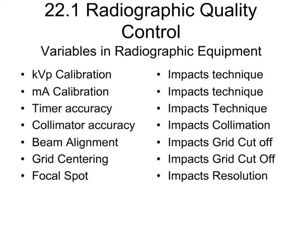
Factors affecting density are • kV • mA • Time • Distance • Thickness and nature of part.
Kilovoltage (kV) : It represent penetrating power of X-ray. More the kV across the tube more power full x-ray produce with more penetrating power. • Milliampere (mA) : Measure of electron flow per second from cathode to anode in X-ray tube. Double the mA double is x-ray exposure rate. • Time : It is related to the amount of X-ray produce More the mA flowing through filament more electrons emitted and more X-rays are produce.
Distance : • The intensity or exposure rate of radiation a given distance from point source is inversely proportional to the square of distance. • Intensity is directly related to density. • ID2 = id2 , for given value of kV and mA.
Radiographic object : • Human body consist tissues and organs with different thickness and density. • Density of objects from greater to least: Dental enamel Bone water density tissue Gas Fat
3. Contrast • Radiographic Contrast is range of density variation among light and dark areas on radiograph. • The difference between density of adjacent areas must be at least 2%to be perceptible to human eye. • Density represent amount of silver deposited in various areas while contrast represent relative distribution of silver in various areas.
Radiographic contrast is of two type : • Long scale (low) contrast • Short scale (high) contrast Low High Contrast Contrast
Radiographic contrast depends on • Subject contrast • Film contrast
Subject Contrast: • Defined as the contrast in aerial image. • Aerial image - spatial distribution of photons in the cross section of the exit beam, which will be recorded on the film as radiographic image. • Aerial image also contain unwanted information in the form of noise which impair quality of image. • These noise factor include : scattered radiation , quantum mottle and fogging,
Subject contrast depend on following factors : • Radiation quality • Radiographic object • Scattered radiation • fogging
Film contrast : • Depends on following factors • Type of image receptor • With or without screen • Processing system.
Type of image receptor (films): • There are special films for long , medium and short scale contrast. • It depends on the composition of emulsion present on radiographic films. • Developing process: • It depends on the compositions of chemicals used for developing films • Temperature during development and time for development also affect film contrast.
4. Distortion • Misrepresentation of true size and shape of object is called distortion • It is not possible to avoid distortion but only minimise as image is two dimensional and object is three dimensional. • Two types of distortion • Size • Shape
Size Distortion • Magnification : • It depends on the distance between source and object. • If distance is more, less magnification and sharper image • If distance is less, more magnification and more burr too.
Magnification Factor source-to-image receptor distance • MF = source-to-object distance • SOD difficult to measure accurately *usually an estimated value SID • MF = SOD
Shape Distortion Depends on: • Object thickness • Object shape • Object position
Object Thickness • Thick objects have more OID and are more distorted than thinner structures
Object Position • If the object plane and the image plane are parallel, the image is not distorted • CR perpendicular to the part
Position Distortion • Foreshortened = anatomy at an incline to the CR displays smaller than true size
Position Distortion • Elongation: anatomy at an incline and lateral to the central axis • Could be foreshortened as well elongation
Position Distortion – Irregular Anatomy • Anatomy or objects can cause considerable distortion when imaged off the central axis
5. “Noise” • Borrowed from electrical engineering • Audio noise = hum or flutter heard from a stereo • Video noise = “snow” on a TV • Radiographic noise = random fluctuation on the OD of the image
Radiographic Noise • Four components: • Quantum mottle, Film graininess, structure mottle & scatter radiation
QUANTUM MOTTLE • Due to non-uniform intensity over the cross section of the x-ray beam as it leaves the tube port. • Hence it exposes different areas of film with different number of photons. • In Slow screen film combination – more photons required for same density • High speed screen film – smaller no of photons can provide the same over all density – Fewer photons reaching the image receptor can cause an undesirable fluctuation in image densities- mottled/grainy appearance.
Quantum Mottle • An image produced with just a few x-rays will have more quantum mottle. • The use of very fast intensifying screens or not enough mAs or kVp will increase quantum mottle
Radiographic Noise • Film graininess – distribution & size of the silver halide grains in the emulsion • Structure mottle – uneven distribution of phosphor • Not under the control of the technologist
Image Noise • Speckled background on the image • Caused when fast screens and high kVp techniques are used. Noise reduces image contrast • The percentage of x-rays absorbed by the screen is the detective quantum efficiency (DQE) • The amount of light emitted for each x-ray absorbed is the conversion efficiency (CE)
Devices and Measures to Improve Radiograph Quality • Removal scattered radiation There are various devices to remove scattered radiation • Grid • Air Gap method • Aperture Diaphragm • Cones • Variable Aperture Beam Limiting Devices(Collimator) • Moving Slit radiograph • Anode Heel Effect
Grids Grid is device made of thin lead strips closely placed separated by radiolucent material. Working of grid: Lead plates in grid absorb scattered X-rays and prevent them from reaching to film
Types of Grid : • Stationary grid • Parallel or non focal grid • Focal grid • Moving grid
Air-Gap (Air Filtration) • Principle • radiation scatters uniformly • decrease in scatter • air gap decreases angle of capture; increases angle of escape • air gap very effective in removing scatter originating closest to film • mAsincreased 10% per cm gap • Magnification results unless SID is increased