Download
1 / 71
710 likes | 728 Vues
This document provides an overview of the beam transport design status and safety review for the 12GeV upgrade. It includes details on injection, reinjection, layouts, stands, girders, and vacuum specifications. The text outlines requirements, specifications, machine development, alignment, and vacuum standards for the upgrade project.

E N D
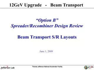
12GeV Upgrade - Beam Transport 2008 Beam Transport Design Status and Safety Review Beam Transport - Layouts, Stands, Girders, Vacuum, etc… Mike Bevins, Ross Bailes & David Green For the Design Team Chase Dubbe, Paul Hansen, Gary Hays, Derrick James, Steve Mano, Floyd Martin, Brent Matsu, Jacki Smith, Dan Spell, Mike Tate, Rick Wolfley & Dennis Zekoff June 3, 2008
Outline • Introduction & Scope • Requirements & Specifications • Machine Development & Configuration Control • Design Status • Injector and Reinjection, N&S Linac – Ross Bailes • Extraction – David Green • Existing Arcs, Spreaders & Recombiners, ARC 10 & Hall D • The Path Forward • Summary
Introduction & Scope • The 12GeV upgrade requires: • Extensive modifications to the injection, five spreader & recombiner, and 2nd extraction regions • New ARC (ARC 10) below the existing ARC 8 on the west side of the machine • New beamline to Hall D tagger building • Installation of ten new upgrade cryomodules • PED effort spans all of FY08 & 09 • ~516 person-weeks (10 person-years) of budgeted labor (engineering & design) • $1.7M in procurements (stands, girders, & vacuum)
Requirements & Specifications Same as last year… • Alignment specs • Quads positioned to +/-0.5mm in x & y, +/- 9mm in z • Dipoles positioned to +/- 0.5mm in x & y, +/- 3mm in z • Vacuum specs • Beam line partial pressure of hydrogen <10-6 torr • Total average pressure of all other constituents less than 5x10⁻⁷ torr • Special Case: Warm region girders between cryomodules - UHV • Fabrication, vacuum welding, cleaning & handling, and leak checking specs still apply • 22631-S-001 Fabrication of Ultra-High Vacuum Equipment • 22632-S-001 Cleaning and Handling of U.H.V. Components • 22633-S-001 Welding Specification For U.H.V. Components • 22634-S-001 Helium Leak Test For U.H.V. Components New: • Jlab structural weld design & inspection guidelines (Jlab EH&S Manual 6122)
Machine Development & Configuration Control • Our challenge on the Layouts, Girders, and Stands front: • To manage the vast number of design changes that must take place to transform the existing machine to the 12GeV machine • To capture ALL quad, corrector, diagnostic, and vacuum element changes we developed the Element Control List (ECL) • Songsheets level layouts have also been developed for 33 sections of the machine • Maintained revision history as machine definition evolved • We have developed and maintain a webpage to consolidate the beam transport design documentation and enhance communication within MEG as well as with our friends throughout the lab (CASA, Power, I&C, Installation, Vacuum, etc.)
Injection & Reinjection – Intro & Scope • To accommodate the new arc 10 line the injector line has been shifted over the transfer lines beginning 20.51m upbeam of the current position • Two existing quad girders have moved over the transfer lines • Three girders already over the transfer lines have been shifted to suit the new optics design • Existing quad girders and diagnostics have been reused • Two new quad girders have been installed b/w the DP station and the 1st BL • The 123MeV spectrometer has been relocated upbeam and the spectrometer branch has been modified from a 20 degree to a 25 degree angle to clear support stands and arc girders • Any upgrades & final configuration pending release of Reza’s TN Injector & Reinjection
Injection & Reinjection – Layouts Current Configuration Existing injector line running under arc 8 Four Quad Girders (2 new, 2 rebuilt on short girders) 12GeV Configuration Shift quad girders upbeam with dipoles BL dipole shifted 20.51m upbeam • VERY congested area • Surveys have been completed in this area to document “as-built” locations of stands Arc 10 four meter dipoles Arc 10 quad girder Spectrometer shifted upbeam
Injection & Reinjection – Selected Images Injector line quad girder Spectrometer line Arc 8 dipole View looking downbeam
Injection & Reinjection – Selected Images Injector line girders over transfer lines
Injection & Reinjection – Layouts He Transfer Lines – Based on survey data Detail of 4 front end girders is shown on following slide 2 existing arc stands will have to be field modified to allow the newly shifted beam tube to pass through them. BL dipole shifted 20.51m upbeam Four Quad Girders (2 new, 2 rebuilt on short girders) Arc 10 four meter dipoles 79” Arc 10 quad girder 2 existing arc stands had to be re-designed due to interferences with 12 GeV girder locations. Spectrometer shifted upbeam 54” As a result of the surveys, the 0R02 Girder was rotated 180 degrees to eliminate the foul with an existing stand and to allow the re-use of an existing girder. 54.5” The floor to ceiling stands shown have been located based on data points gathered by the survey and alignment group
Injection & Reinjection – First 4 Girders Detail of typical QD girder shown on following slide Plan View Elevation View
Injection & Reinjection – Typical Girder Assy Beam Direction Beam Direction The first four girders utilize the same extruded channel profile that is used for the warm region girders. This allows for the use of existing bracketry e.g. cross-bars, v-blocks, etc.
Injection & Reinjection – Layouts Quad girders BL dipole Current Configuration BL dipole to replace DK (moved 20.51m upbeam) No change to this BL dipole or girder Shift existing girders Existing injector line girders relocated over transfer line 12GeV Configuration
Injection & Reinjection – Layouts BL dipole to replace DK (moved 20.51m upbeam) Shift existing girders Detail of SLM chamber on following slide Existing injector line girders relocated over transfer line Plan View Elevation View Since there were only z-translations, the level of detail for the girders over the transfer lines was minimized
Injection & Reinjection – SLM Assembly ME Group worked closely with CASA and the machine shop to develop and design the SLM chamber for the 2nd BL that would allow for easy fabrication, alignment and calibration.
Injection & Reinjection – Layouts Current Configuration No changes between dipoles Modified re-injection chicane girder 12GeV Configuration
Injection & Reinjection – Reinjection Chicane • Re-injection chicane girder modifications • Replaced dipoles with higher strength CB magnets • Used existing support stand • Modified existing support plate to accommodate new magnets
Injection & Reinjection– Reinjection Chicane New CA* New CB* Re-use of existing stand and support plate. The support plate will be machined to accomodate new mounting bracket locations. * The final design of the CB and CA magnets are not complete. The configuration shown is preliminary.
Injection & Reinjection – ’07 Scope Comparisons • Initial scope assumed the re-use of the 2 stands for the girders making the transition over the transfer lines 0R01 and 0R02. • - Based on field surveys and the decision to rotate the 0R02 girder 180 degrees, the 0R02 stand cannot be used. A new stand is required. The 0R01 stand will be re-used. • Initial scope assumed the re-use of the 2 stands used to support the 1L00 and 1L01 girders in the N. Linac. These stands cannot be used but we will be replaced with the 2 stands from injector line currently used to support the 0L09 and 0L10 girders. These two girders have been shifted over the transfer lines. No cost changes associated with this change-out. • Initial scope assumed that 4 new vertical support stands would be required to accommodate interferences between the arcs and the injection area. After field surveys, only 2 new stands are required with straight forward field modifications to 3 additional stands.
Injection & Reinjection – Remaining Work/Summary Summary: • 3D model is complete. • Songsheets have been developed • Installation and alignment coordinates have been generated. • 99% of drawings have been signed off and are ready for procurement, see remaining work for missing 1%. • New Drawings: 41 • Revised Drawings: 9 Where to from here: • Design and layout work for the spectrometer branch has progressed based on discussions held in January of this year. We are expecting no surprises from Reza’s TN. Drawings ready for signature pending review of the TN. • Detail design work has also been completed for the mini-chicane girder. • Drawings will be issued pending completion of CB magnet design. • Formally document welds in accordance with JLAB EH&S 6122 • Procurement Activities: Planning, Scope of Work Documents, etc.
North & South Linacs – Intro & Scope • North Linac 1st Section • QB to QC change at MQB1L00 & 01 • N&S Linac Sections 3 & 4 • Add new modules in zones 22 through 25 • Replace warm region girders with new short girder • 12GeV field strength requirements forced us to replace two QB quads at the start of the linac with QCs and replace the dipoles on the re-injection chicane girder with higher strength magnets • The12GeV upgrade requires an additional ten cryomodules • Five in the north linac and five in the south • NEW modules are longer than the original CEBAF modules • Result: Warm region girders downstream of the new modules must be replaced with a new short girder • Like downstream of SL21
North & South Linac – NL,QB to QC Change • MQB1L00 & MQB1L01 girder modifications • Replaced QB quads with higher strength QCs • Re-used support pedestals from 2 injector line girders that have been re-positioned over the transfer lines. View looking upbeam to MQB1L00 & 01 girders MQB1L00 MQB1L01
North & South Linac – NL,QB to QC Change New QC’s that replace existing QB’s These 2 stands are re-used from the 2 injector girders , 0L09 and 0L10, that got moved across the transfer lines. The existing stands have been field modified with outriggers that do not support the new girders.
North & South Linac – New Module/Girder Layouts Layout of new modules & girders in linac DP station moved to end of linac Current Configuration (Zones 19 – 22) 12GeV Configuration (Zones 19 – 22) New module Replaced module baseplates Current Configuration (Zones 23 – 26) 12GeV Configuration (Zones 23 – 26) Five New warm girders Four New modules
North & South Linac – Warm Region Girders • Warm girder design was reviewed in Oct 2004 • Prototyped and installed at SL21 • Designed to accommodate multiple combinations of cryomodule configurations • Quad, BPM, and alignment cartridges will be reused on new short girders H&V nested Air Core correctors over BPM Viewer & pump drop cross Quad New stand Existing baseplate New short warm region girder Old warm region girder
North & South Linac – Summary/Remaining Work Summary: • Detailed design and drawings for the 1L00 & 1L01 girders is complete • Songsheets have been developed • Installation and alignment coordinates have been generated. • Warm girder design and associated detail drawings are complete • No scope changes from last year
Extraction – Intro & Scope • The extraction region must be upgraded to support transport of higher energy beam to halls A, B, & C and 5th pass beam to the new arc 10 to support 12GeV operations Extraction Region
Extraction – RF Separators Current Configuration 12GeV Configuration New quad girder New quad girder Relocated New Two new pedestal stands Existing supports
Extraction – RF Separators Two new pedestals Existing supports (gray)
Extraction – Septa Magnet Stacks Current Configuration 12GeV Configuration New quad girder Two new support stands Relocated Two YBs One relocated and one new support stand New Three YRs Two new pedestal stands YA Septa Stacks YB/YR Septa Stack
Extraction – Quad Girder • New AE01 Girder • Replaces existing hall transport girder New pedestal stands not required -existing stands have 5 arms
Extraction– YASepta Magnet Stacks Two relocated supports New pedestal stand for AE02 girder Two new pedestal stands
Extraction – YB/YR Magnet Stacks Existing YB septa magnets New downbeam support stands Three YR septas (recycled from S&Rs) New upbeam support stand
Extraction – Dipole Magnet Stacks Current Configuration 12GeV Configuration New Two new support stands Three BPs New BP Dipole Stack
Extraction – Dipole Magnet Stacks Current Configuration 12GeV Configuration New
Extraction – Dipole Magnet Stacks 12GeV Configuration Two existing BQs New support stand Three new BPs New New BP New pedestal for 5th pass BP downbeam support Two new pedestal supports for 5th pass BP BQ/BP Dipole Stack BP Dipole Stack
Extraction – BPDipole Magnet Stacks ATLis task in place to gather as-built locations of ceiling penetrations in this area One new pedestal stand Two new support stands
Extraction - Dipole Magnet Stacks /Arc Recirculation New Arc 10 four meter dipole New stand rotated to accommodate new BP stack New pedestal stand for Arc 10, AA01 girder
Extraction – BQ/BPDipole Magnet Stacks Two existing BQ dipoles New upbeam stand Three new BP dipoles New downbeam stand. This stand will have two 1-hole arms for BQ and three 2-hole arms for BPs.
Extraction – Septa Magnet Stacks Existing YA Septa Stack Existing YB Septa Stack
Extraction – Dipole Magnet Stacks BP Stack BQ Stack Existing BQ Dipole Stack Existing BP Dipole Stack
Extraction – ‘07 Scope Comparisons • Initial scope called for adding a QB to the 8E01 and installing a QB/QC girder at AE01. Final design leaves 8E01 as is and installs single QC at AE01 • Initial scope for YA magnets was to add one new support and one relocated support. Final design uses two relocated supports from the existing YB stack. • Initial scope specified two new pedestal supports for the downstream 5th pass BP magnet. This has been modified to utilize a single pedestal stand due to space constraints. • The 5th pass BP pedestal for the BQ/BP stack has been eliminated in favor of a new stand designed to accommodate BQ and BP supports.
Extraction – Remaining Work/Summary • Summary: • 3D model of extraction region is 80% complete • Detail design work has been completed for several of the new/relocated support stands • Where to from here: • Awaiting updated optics deck from CASA to… • Complete extraction and recirculation layouts • Begin YR vacuum chamber design • Update songsheets to reflect change to single quad girders at 8E and AE01 and add RF Separator calibration magnets to 12 GeVsongsheet • Formally document welds in accordance with JLAB EH&S 6122
Existing Arcs & Hall Transport– Intro & Scope • Accommodate the addition of the H-steel on Arc dipoles • Swap QA quad with QR at 32 locations • Install new correctors on 3 girders • Develop songsheets that reflect 12GeV quad, corrector, and power supply upgrades West ARC Dipoles
Existing Arcs - H-style dipole interface Prototype H-style dipole • H-steel interferes with existing outrigger support • H-steel runs directly through the holes tapped into the magnet core used to support the outrigger • Prefer not to cut away H-steel to clear existing support • Solution proposed last spring will be revisited based on H steel configuration change INTERFERENCE
Existing Arcs – Existing Alignment Scheme • Existing C-style dipole alignment scheme • Alignment fixture indexes on machined flats on each end of the magnet • Two bolts are used to fasten the fixture to the magnet (mounting holes tapped into upper machined surface on the magnet core) • Problems - • Lab alignment group reports that it can be difficult to ensure that the fixture is seated properly against the magnet • Scheme only provides two alignment points on each magnet • Fixtures would require modification to eliminate interference with new H-steel dipoles Machined flats Existing C-style ARC dipole Prototype H-style dipole Existing C-style dipole up-beam alignment fixture dipole
Existing Arcs – New Alignment Scheme • Use threaded retro-reflector nests in old fixture fastening holes • Provides four points for alignment • Alignment group has done mock-up to confirm line-of-sight with the addition of H-steel • Plan uses tapped holes on the machined flats that were not intended as alignment reference • The Alignment group measured 28 dipoles of four different styles during the summer 2007 shutdown • Results show no significant problems with repeatability of the target Retro-reflector nest C-style ARC dipole with retro-reflector nests installed