Download
1 / 16
160 likes | 344 Vues
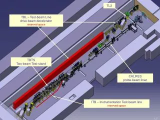
CTF3 Probe Beam Status. 1. What is CALIFES ?. Probe beam LINAC for the TBTS. TL2’. TBL decelerator. CALIFES. Two-Beam Test Stand. The CTF3 Facility. Inside the CLEX building. 2. CALIFES layout. CALIFES in the CLEX. CALIFES Layout. Based on: Photo-injector (LAL Orsay)

E N D
CTF3 Probe Beam Status Califes CTF3 probe beam - Wilfrid Farabolini 1
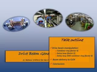
What is CALIFES ? Probe beam LINAC for the TBTS TL2’ TBL decelerator CALIFES Two-Beam Test Stand The CTF3 Facility Inside the CLEX building Califes CTF3 probe beam - Wilfrid Farabolini 2
CALIFES layout CALIFES in the CLEX CALIFES Layout • Based on: • Photo-injector (LAL Orsay) • Laser line (using the same laser as for PHIN) • 3 former LIL accelerating structures • A single klystron 45 MW, RF distributed to the structures and the gun through WG, splitters, phase-shifter and attenuator. • A complete set of diagnostics Newly installed 3GHz power phase shifter (Franck Peauger and al. IRFU Saclay) Califes CTF3 probe beam - Wilfrid Farabolini 3
Laser, bunch charge and QE 0.12 nC Photo-injector developed by LAL QE, bunch charge and laser energy 3 months record • CsTe photo-cathode quantum efficiency was measured around 1% only during few days after regeneration one year ago. • Now it varies between 0.2 and 0.6 % (depending on laser spot position). • Laser beam needs to be shaped by a hard aperture thus limiting energy per pulse around 250 nC. • In order to achieve reliably the requested bunch charge (0.6 nC) a dedicated laser system with a short beam transport line and capable to deliver 1 mJ per pulse is under development CsTe photo-cathode Shaped laser profile on virtual cathode [see next talk by Marta] Califes CTF3 probe beam - Wilfrid Farabolini 4
Laser and beam stability Strong correlation between laser energy and beam charge fluctuations Beam position and size jitters • Laser energy and beam charge fluctuate accordingly around 4 % rms. • Beam position at gun output also fluctuates by 0.1 mm (1s) • Again a dedicated laser with a short beam transport will help to fix the problem. [Marta’s talk ] Califes CTF3 probe beam - Wilfrid Farabolini
Energy Energy measured with CALIFES and with TBTS spectrometer lines Energy measured with beam deviation by correctors • Discrepancy between energy values provided by the 2 spectrometers lines: DE = 10.3 MeV, (5.6 %) • Correctors beam displacements vs. current agree with the TBTS one. • Max energy is obtained with buncher on crest acceleration but at the expense of bunch length Califes CTF3 probe beam - Wilfrid Farabolini 6
Expected energy Energy as function of buncher phase shifter position Forward power levels from RF couplers • Compressed pulse (1.2 ms) : 138 MW peak (from 45 MW 5.5 ms klystron) • RF network loss : 1.5 dB • Considering the energy gain theoretically provided by the LIL structure • E [MeV] = 15.34 (P [MW] )1/2 - 0.087 I [A] • The maximum energy expected should be 215 MeV not 185 MeV • The reason of this discrepancy is still under investigation (phase shift due to the pulse compression ?) • In addition buncher phase/energy scans do not fit with a sinus law (bunch drift in the buncher at low b ?) Califes CTF3 probe beam - Wilfrid Farabolini
Energy spread Settings with very low energy spread Energy spread around 1% FWHM Settings with large energy spread separating various bunches • Energy spread can easily be lower than ± 0.5 % by tuning accurately RF phases in gun and structures. Califes CTF3 probe beam - Wilfrid Farabolini
Emittance Control screen during quad scan Horizontal / vertical quadrupole scan fit and derived beam parameters • Emittance was sometimes measured below 20 mm.mrad, other times much higher (> 40 mm.mrad). • Quad scan data are difficult to obtain due to the small waist size (<0.1mm) and require the use of the OTR screen with a high optical magnification. • Settings to minimize the emittance are not straightforward to obtain Califes CTF3 probe beam - Wilfrid Farabolini 9
Compression Accélération Bunch length Laser pulse length measured with a streak camera Velocity bunching scheme Deflecting cavity Thanks to A. Dabrowski and M. Csatari • 3 GHz Phase calibration gives 0.94 mm per degree (333 ps for 360 deg) • Vert. beam size due to the deflecting cavity: • 1.45mm • -> Bunch length 1.42 ps at 1 s or 3.34 ps FWHM Cavity OFF sy = 0.24 mm Cavity ON sy = 1.47 mm • Bunches produces by the photo-injector need to be shorten using the first LIL structure on the raising slope. • To measure bunch length, a deflecting cavity is used at zero crossing that allows to enlarge the vertical beam size as function of bunch length. Califes CTF3 probe beam - Wilfrid Farabolini 10
Bunch length measurement with ACS zero crossing: no energy variation But energy spread increase ACS 12GHz OFF ACS 12GHz On at zero crossing • The 12 GHz accelerating structure can be used to measure the bunch length, even more efficiently than the 3 GHz deflecting cavity. • Measures done for various phases of the buncher give pulse length scaling from 1.46 ps to 5.6 ps. Califes CTF3 probe beam - Wilfrid Farabolini
Cameras degradation due to radiations 0.2 mm 0.1 mm 0.05 mm Camera close to the dump at the installation The same camera after 2 months Pattern included in the screen MTV0790 showing the lead shielding and the LED lighting • Despite the thick lead shield (5 to 10 cm), cameras close to the TBTS dumps have suffered from radiations: high noise on CA.MTV0790 and no more signal from the CM.MTV0590. • But the degradation is now stabilized, so it probably happened during a severe drive beam loss operation. Califes CTF3 probe beam - Wilfrid Farabolini
Probe beam operational for TBTS studies User friendly control panels (Martin Nybo EN / ICE) Good beam transport through TBTS 130 deg : Pb in phase shifter 180 deg : OK Capability to change the probe beam phase vs. drive beam Energy gain and energy spread vs. phase Califes CTF3 probe beam - Wilfrid Farabolini
CALIFES foreseen improvements • A dedicate laser system • Accurate calibrations of the spectrum line, phase shifters, RF couplers… • Extensive use of the BPMs (presently displacements are not calibrated) • Installation of an RF pick-up to monitor the bunch length • Installation of a moving slot in front of the first screen to measure gun emittance • Development of a beam dynamic model type “flying simulator” • Possible construction of a instrumentation test beam line (ITB) parallel to the TBTS (manifestations of interest are welcomed) Califes CTF3 probe beam - Wilfrid Farabolini 14
Beam dump to be removed 8 m 0.43 m 35 deg CLIC Module footprint 1.45 x 2.1m 2.0 m 2.0 m 1.0 m 1.0 m 8.0 m 20 deg 0.7 m CLIC Module transport The Instrumentation Test Beam project • First step: record the potential users for this line with their requirements in terms of performances and ancillaries. (Anne’s talks about CTF3 instrumentation, opportunities and limitation, WG6). • Not necessary the actual CALIFES performances: thanks to the chicane pulse length as short as 20 mm could be obtained (Volker’s study Short Pulse Capabilities of the Instrumentation Beam Line, Uppsala University 6 may 2010). • Feasibility, beam dynamic, drawings, equipments collections, construction… Califes CTF3 probe beam - Wilfrid Farabolini
Conclusions • CALIFES probe beam is now routinely used for the TBTS operations and provides useful and trusty data about ACS behaviour. • Good beam parameters are reasonably easy to obtain and then are stable in time. • The operations suggest improvements in some characteristics that will be developed this year. Many thanks to so many people from CERN and from the collaborations who have continuously shown their supports and encouragements. Califes CTF3 probe beam - Wilfrid Farabolini 16