Download
1 / 36
360 likes | 530 Vues
CLIC/CTF3 status, results and plans. Frank Tecker for the CLIC study team Introduction Status of feasibility demonstration Conclusion http:// cern.ch /CLIC-study. Path to higher energy. Collider History : Energy constantly increasing with time Hadron Collider at the energy frontier

E N D
CLIC/CTF3status, results and plans Frank Tecker for the CLIC study team Introduction Status of feasibility demonstration Conclusion http://cern.ch/CLIC-study
Path to higher energy • Collider History: • Energy constantly increasing with time • HadronCollider at the energy frontier • Lepton Collider for precision physics • LHC online now • e-/e+ storage ring excluded by synchrotron radiation • Consensus to build Lin. Collider with Ecm> 500 GeV to complement LHC physics(European strategy for particle physics by CERN Council)
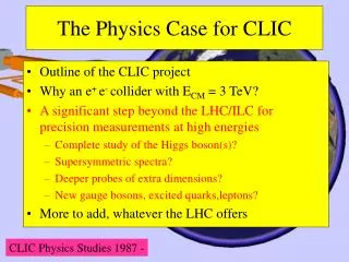
TeV e+e- physics • Higgs physics • Tevatron/LHC should discoverHiggs (or something else) • LC explore its properties in detail • Supersymmetry • LC will complement the LHC particle spectrum • Extra spatial dimensions • New strong interactions • . . .=> a lot of new territory to discoverbeyond the standard model • “Physics at the CLIC Multi-TeV Linear Collider”CERN-2004-005 • “ILC Reference Design Report – Vol.2 – Physics at the ILC”www.linearcollider.org/rdr
CLIC – basic features • e-/e+ collider up to 3 TeV collision energy Luminosity > few 1034 cm-2s-1 • High acceleration gradient (100 MV/m) • “Compact” collider – total length < 50 km • Normal conducting acceleration structures • High acceleration frequency (12 GHz) • Two-Beam Acceleration Scheme • High charge e-Drive Beam (low energy) • Low charge Main Beam (high collision energy) • => Simple tunnel, no active elements • => Modular, easy energy upgrade in stages CLIC TUNNEL CROSS-SECTION 4.5 m diameter Transfer lines Drive Beam Main Beam e- Drive beam – 101 A, 240 ns from 2.4 GeV to 240 MeV e+/e- Main beam – 1 A, 156 ns from 9 GeV to 1.5 TeV
CLIC – overall layout 3 TeV Drive Beam Generation Complex Drive beam Main beam Main Beam Generation Complex
Delay Loop x 2 gap creation, pulse compression & frequency multiplication Drive Beam Accelerator efficient acceleration in fully loaded linac RF Transverse Deflectors Combiner Ring x 3 pulse compression & frequency multiplication Combiner Ring x 4 pulse compression & frequency multiplication CLIC RF POWER SOURCE LAYOUT Drive Beam Decelerator Section (2 x 24 in total) Power Extraction Drive beam time structure - final Drive beam time structure - initial 240 ns 240 ns 5.8 μs 140 μs train length – 24 x 24 sub-pulses 4.2 A - 2.4 GeV – 60 cm between bunches 24 pulses – 101 A – 2.5 cm between bunches CLIC Drive Beam generation Drive Beam Generation Complex Drive beam
Lemmings Drive Beam AlexandraAndersson
World-wide CLIC&CTF3 Collaboration 39 Institutes from 20 countries Aarhus University (Denmark) Ankara University (Turkey) Argonne National Laboratory (USA) Athens University (Greece) BINP (Russia) CERN CIEMAT (Spain) Cockcroft Institute (UK) ETHZurich (Switzerland) Gazi Universities (Turkey) John Adams Institute/RHUL (UK) JINR (Russia) Karlsruhe University (Germany) KEK (Japan) LAL / Orsay (France) LAPP / ESIA (France) NCP (Pakistan) Nikhef (Netherlands) North-West. Univ. Illinois (USA) Patras University (Greece) Polytech. University of Catalonia (Spain) PSI (Switzerland) RAL (UK) RRCAT / Indore (India) SLAC (USA) Thrace University (Greece) Tsinghua University (China) University of Oslo (Norway) Uppsala University (Sweden) UCSC SCIPP (USA) Helsinki Institute of Physics (Finland) IAP (Russia) IAP NASU (Ukraine) IHEP (China) INFN / LNF (Italy) Instituto de Fisica Corpuscular (Spain) IRFU / Saclay (France) Jefferson Lab (USA) John Adams Institute/Oxford (UK)
ILC – CLIC collaboration • Extremely fruitful collaboration between CLIC and ILC • Taking advantage of common issues and great synergies • Common International Workshop on Linear Colliders IWLC2010for accelerator and detectors18-22/10/2010 @ CERN http://cern.ch/LC2010 • Towards single Linear Collider community and…. • Possibly future joined project based on Physics requests (LHC results) and technology choice as best trade off between performance, maturity, risk, cost, etc….
CLIC Plan – CDR => TDR • Identified critical issues divided into three categories (endorsed by ACE) • Feasibility issue: Failure to solve implies that CLIC technology is fundamentally not suited to build a machine of interest for high energy physics • Performance issue: can compromise the performance • Cost issue: has significant impact on cost • CDR concentrating on addressing feasibility issues (mid 2011 to CERN council) • Targeted conclusion: worth to make a technical design of such a machine • A baseline is being developed, involving many new experts • Will have turned the feasibility issues mostly into performance issues • Programme is in place and needs some continuation afterwards • A number of important performance and cost issues addressed • Technical design (TDR) phase with more details (2016/2020?) • Targeted conclusion: One can propose this very design as a project • Addressing the performance issues • Reducing cost • Work plan for the TDR phase is being finalised
10 CLIC Feasibility Issues • RF Structures (gradient + power generation): • Accelerating Structures (CAS) • Power Production Structures (PETS) • Two Beam Acceleration(power generation and machine concept): • Drive beam generation • Two beam module • Drive beam deceleration • Ultra low beam emittance and beam sizes (luminosity): • Emittance preservation during generation, acceleration and focusing • Alignment and stabilisation • Detector (experimental conditions): • Adaptation to short interval between bunches • Adaptation to large background at high beam collision energy • Operation and Machine Protection System (robustness)
Combiner Ring – 84m Delay Loop – 42m TL1 Laser CLEX TL2 CLIC Test Facility - CTF 3 demonstrate Drive Beam generation (fully loaded acceleration, bunch frequency multiplication 8x) Test CLIC accelerating structures Test power production structures (PETS) Bunch length chicane 30 GHz “PETS Line” RF deflector Injector Linac 4A – 1.2µs150 MeV 32A – 140ns150 MeV 30 GHz test area • 2003 Injector + part of linac • 2004 Linac + 30 GHz test stand • 2005 Delay Loop • 2006/07 TL1 + Combiner Ring • 2008/09 New photo-injector, TL2 + CLEX
Accelerating Structure Results • RF breakdownscan occur=> no accelerationand deflection • Goal: 3 10-7/mbreakdowns at 100 MV/m loaded at 230 ns • T18 and TD18 structures built and tested at SLAC and KEK • T18 reached 95-105 MV/m • Damped TD18 reaches anextrapolated 85 MV/m • Second TD18 under test at KEK • Pulsed surface heating expected to be above limit • CLIC prototypes with improveddesign (TD24) will be tested this year • expect similar or slightly better performances S. Doebert et al. Breakdown probability (1/m) CLIC goal Average unloaded gradient (MV/m)
PETS Results • Beam based (with recirculation): • Power >130 MW peak at 150 ns • Limited by attenuator and phase shifter breakdowns(cleaned for this run) • Power production according to predictions • Klystron based (SLAC): • achieved: 137 MW/266 ns/1.2 10-6 BDR • target: 132MW/240ns/10-7 • Structures had damping slots but no damping material • Novel design on-off mechanism will be tested this year • More testing is needed
Drive Beam generation (1) • efficient acceleration needed • => fully loaded operation • Full beam loading operation routinely demonstrated • Current stability in drive beam accelerator close to target(1.5 10-3 vs. 0.75 10-3) • Further improvement possible • simulated feedback: 0.6 10-3 Measured RF-to-beam efficiency 95.3% Theory 96%(~ 4 % ohmic losses)
Drive Beam generation (2) • Full factor 8 combination (DL+CR) demonstrated • improvements in current and beam properties to be done Current from Linac Current after Delay Loop Current in the Combiner Ring
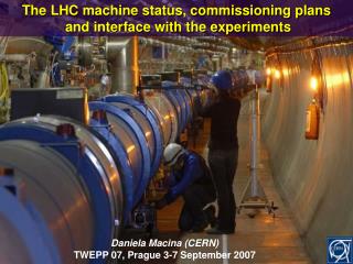
Fire in CTF3 Klystron Gallery • On March 4a fire destroyed the pulse forming network in the faraday cage of MKS13 • Cleaning of components was needed to prevent corrosion • => ~4 months delay • klystron missing => lower beam energy or lower beam current • restart went well without any major problems
Drive Beam Deceleration and Module: CLEX • CLIC Decelerator sector: ~ 1 km, 90% of energy extracted • Two-beam Test Stand (TBTS): • Single PETS with beam • Accelerating structure with beam • wake monitor • kick on beam from break down • Integration • Test Beam Line (TBL): • Drive beam transport (16 PETS) • beam energy extraction and dispersion • wakefield effects Califes: Probe beam photo-injector Beam energy 175 MeV
Two Beam Module • Integration aspects are important • alignment • vacuum • transport • cabling • … • Beam tests of PETS are ongoing • accelerating structure installed • important goal 2010: two-beam acceleration with 100 MV/m • Some tests after 2010e.g. wake monitors, design exists • Later full modules will be tested G. Riddone et al.
First two-beam acceleration in CTF3 • Principle had been established in CTF and CTF2 • probe beam initial energy = 175.2 MeV • Energy gain provided by ACS = 4.3 MeV • Power entering in the ACS is about 3.5 MW • just the beginning of conditioning of the accelerating structure Spectrometer line screen drive beam ON drive beam OFF => mm mm
Drive Beam Deceleration • Drive beam has high current (100A) and large energy spread • Simulations show that the beam is stable • Several iterations of PETS design • Test Beam Line (TBL) under construction will increase confidence • the first PETS installed (3 for end 2010) • beam to the end E. Adli et al. Oslo Univ. / CERN 22
Ultra Low Beam Emittances/Sizes • Designs for critical lattices exist achieving target performances • Critical beam physics issues are being addressed in time for CDR • E.g. electron cloud, intra-beam scattering, fast beam ion instability, RF stability, beam-based alignment, stability and feedback • Specification for critical hardware exists • Design exist of key components and tests are ongoing/planned (alignment system, mechanical stabilisation systems, phase stabilisation systems, DR wigglers, ML quadrupoles, final doublet, instrumentation …) • Also detailed studies for baseline design, e.g. cabling and power supplies • Very important issue are imperfections • Key issue are the alignment and stabilisationhardware performances
Important Example: Element Stabilisation • Tight tolerances on magnet mechanical stability • main linac ~1nm • final doublet ~0.2nm • correlations matter • Beamlineelements move • ground motion (site dependent) • technical noise • Minimise impact of motion by • technical noise identification/minimisation • support/component design • active mechanical stabilisation (m.f.) • beam-based orbit feedback (b.) • motion sensor based feed-forward (ff.) on beam • intra-pulse IP feedback • Chose tools according to needs • LEP tunnel without technical noise would only need beam-based feedback K. Artoos et al
CLIC Detector Issues • Detector requirements close to those for ILC detectors • First studies indicate that ILC performances are sufficient • Adapt ILD and SID concepts for CLIC • Close collaboration with validated ILC designs • Differences to ILC • Time structure (0.5ns vs. 370ns) • Larger beam energy loss • Higher background • High energy • Small bunch spacing • Other parameters are slightly modified • Crossing angle of 20 mrad (ILC: 14 mrad) • Larger beam pipe radius in CLIC (30mm) • Slightly denser and deeper calorimetry • Linear collider detector study has been established at CERN beginning of 2009 (led by L. Linssen, see http://cern.ch/lcd) More in the following talk …
Conclusion • CLIC Conceptual design is advancing well • Baseline choices have been finalised • Feasibility issues are being addressed • Overall good progress but will have to continue after CDR in 2011 • Verify conceptual design with experiments • Project preparation is ongoing -> feedback on design • Cost study • Schedule • Site studies • The TDR phase is being prepared • Future decision on linear collider based on LHC results • Hope for exciting discoveries at LHC • Thanks to everyone I used some material from
Generic Linear Collider C.Pagani Main LinacAccelerate beam to IP energy without spoiling DR emittance Final FocusDemagnify and collide beams Collimation SystemClean off-energy and off-orbit particles Bunch CompressorReduce σz to eliminate hourglass effect at IP Damping RingReduce transverse phase space (emittance) so smaller transverse IP size achievable Positron TargetUse electrons to pair-produce positrons Electron GunDeliver stable beam current
Accelerating gradient • Normal conducting cavities:higher gradient with shorter RF pulse length • Superconducting cavities:lower gradient with long RF pulse • Superconducting cavities fundamentally limited in gradient by critical magnetic field => become normal conducting above • Normal conducting cavities limited in pulse length + gradient by • “Pulsed surface heating” => can lead to fatigue • RF breakdowns (field collapses => no acceleration, deflection of beam) WARM SC
Bunch structure • SC allows long pulse, NC needs short pulse with smaller bunch charge 2625 0.370 ILC 970 ILC 20000 0.0005 312 12 0.156
Delay Loop Principle double repetition frequency and current parts of bunch train delayed in loop RF deflector combines the bunches
injection line 1st turn 2nd septum 1st deflector 2nd deflector local inner orbits λo RF deflector field 4rd 3rd λo/4 RF injection in combiner ring combination factors up to 5 reachable in a ring Cring = (n + ¼) λ
2 1 3 Two-beamacceleration Counter propagation from central complex Instead of using a single drive beam pulse for the whole main linac, several (NS = 24) short drive beam pulses are used Each one feed a ~880 m long sector of two-beam acceleration (TBA) decelerator sector main linac main beampulse pulse 2 pulse 1 From central complex Counter flow distribution allows to power different sectors of the main linacwith different time bins of a single long electron drive beam pulse The distance between the pulses is 2 Ls = 2 Lmain/NS (Lmain= single side linac length) Initial drive beam pulse length tDB is given by twice the time of flight through one single linac so tDB = 2 Lmain / c, 140 µs for the 3 TeV CLIC R.Corsini
~20 km CLIC Layout at various energies Linac 1 I.P. Linac 2 0.5 TeV Stage Injector Complex 4 km 4 km ~13 km 1 TeV Stage Linac 1 I.P. Linac 2 Injector Complex 7.0 km 7.0 km 3 TeV Stage Linac 1 I.P. Linac 2 Injector Complex 21.1 km 2.75 km 2.75 km 21.1 km 48.4 km
CLIC Parameters and upgrade scenariohttp://cdsweb.cern.ch/record/1132079/files/CERN-OPEN-2008-021.pdf 4th phase: 3 TeV luminosity upgrade 3 TeV nominal parameters 2nd phase: 500 GeV luminosity upgrade 500 GeV nominal parameters 3rd phase: 0.5 to 3 TeV energy upgrade 3 TeV conservative parameters 1rst phase: Initial operation 500 GeV conservative parameters J-P.Delahaye