Download
1 / 32
320 likes | 507 Vues
Status of CTF3. G.Geschonke CERN/AB. Collaborating institutes. 17 members involving 22 Institutes. * India and Pakistan have not signed the CTF3 MoU, but have an agreement with CERN for the development of novel accelerator technologies. Draft MoU Addendum with J.Adams Institute London.

E N D
Status of CTF3 G.Geschonke CERN/AB CTF3 Collaboration Board 22.6.2007
Collaborating institutes 17 members involving 22 Institutes * India and Pakistan have not signed the CTF3 MoU, but have an agreement with CERN for the development of novel accelerator technologies Draft MoU Addendum with J.Adams Institute London Discussions with : Iran, UK (Cockcroft Institute), JLAB, EPFL, INFN Milan Past collaboration with RAL within PHIN CTF3 Collaboration Board 22.6.2007
Beam up to here Combiner Ring being commissioned Present status 2004 2005 Thermionic gun Linac DL CR 2006 2007 30 GHz production (PETS line) and test stand CLEX2007-2009 building in 2006 Photo injector / laser tests from 2006 2007 TL2 2007 ? Beam into CLEX in 2008 CTF3 Collaboration Board 22.6.2007
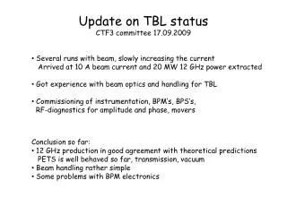
Combiner ring - latest status We make up to a few 100 turns! • Nominal isochronous optics • RF injection • short RF pulse in deflector that it’s only seen by the beam at injection. Switching on the SHBS (2 out of 3) We got immediately the same Transmission in CR!
280 ns 280 ns Combiner ring - latest status Latest results from last week … we recombine (factor 2)! Second turn of second pulse and partly third turn of first pulse Recombination – factor 2 • nominal isochronous optics • energy ~ 115 MeV • RF injection (2nd RF deflector off – so far) • set up of the path length in CR with wiggler
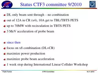
start according to schedule, many operational problems. (controls, magnets,.....). Beam circulated in CR, injected with RF, no recombination yet CTF3 Collaboration Board 22.6.2007
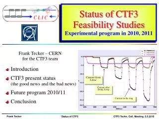
-5 0 5 DP/P (%) Transient Two-beam 30 GHz power production in CTF3 High-gradient test stand, CTF2 Steady state High-power transfer line 100 200 300 400 Time (ns) CTF3 linac Ebeam E0 PETs branch E0 /2 steady state tfill t 30 GHz RF production operation for 30 GHz now routine, largely automatic. Supervision from CCC 24 hour operation / night operation Linac Beam 2007: ● 30 GHz conditioning has started as foreseen. ● 12. May Vacuum leak in PETS line. ● Repaired successfully, operation resumed on 23. May. PETS was not allowed by safety. ● 30 GHz operation Resumed Friday 15.6 ● operate with 5 Hz, then gradually increase frep CTF3 Collaboration Board 22.6.2007
Present status Combiner Ring finished, Commissioning in progress. Preparations for TL2 and TL2’ Optics finished, detailed layout close to completion Procurement of components has started: support infrastructure, vacuum chambers ( India, industry), power supplies, magnets (available/Lure/Celsius/Ciemat), beam diagnostic equipment (CERN, INFN, LAPP) tail clipper (CIEMAT,CERN) Installation in July, August and from November onwards. Target to send beam into CLEX after winter shut-down ~ April 2008 CTF3 Collaboration Board 22.6.2007
25.10.2006 31.8.2006 CLEX building June 2006 Jan 2007 Construction on schedule, lower level finished, equipment is being installed. klystron gallery will be finished in a few weeks. Full electrical power will only be available from end October , meanwhile provisional installation with limited power CTF3 Collaboration Board 22.6.2007
Ongoing work for CLEX CIEMAT magnet movers, PETS prototype,(+ series ????), PETS tank (series ???) UPC & IFIC : BPM development + electronics (series ???) CERN overall responsibility, optics, RF equipment, diagnostics, infrastructure, quadrupoles ??? CEA Dapnia Saclay overall responsibility CERN CEA laser beam line, laser beam conditioning LAL RF gun for photo injector Instrumentation Test Beam Line not presently funded (FP7 GADGET proposal) Uppsala University Two Beam Test Stand CERN PETS and Accelerating structure Pakistan: stainless steel vacuum components + ??? Iran: RF + Beam dynamics simulations CTF3 Collaboration Board 22.6.2007
200 MeV bunch charge 0.5 nC number of bunches 1 - 64 K steerer position monitor profile monitor C A L I F E S A. Mosnier, CEA Dapnia Probe Beam Planning foresees everything to be installed by April 2008 one LIL section radioactive waveguide components missing Laser RF pulse compression 2 x 45 MW beam dump 10 20 25 25 quadrupoles 17 MV/m acceleration 17 MV/m acceleration 15 MV/m compression rf gun cavity focusing coils LIL sections RF deflector spect. magnet CTF3 Collaboration Board 22.6.2007
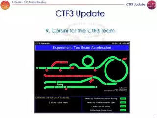
Two Beam Test Stand Accelerate Probe Beam with 30 GHz power from Drive Beam Accelerating structure Spectrometers Diagnostics for energy, transverse kick due to RF breakdown Probe Beam PETS everything to be installed by April 2008 Drive Beam V.Ziemann, Uppsala University CTF3 Collaboration Board 22.6.2007
Two Beam Test Stand CTF3 Collaboration Board 22.6.2007
Test Beam Line TBL Demonstrate beam stability under deceleration PETS design 5 MV/m deceleration (35 A) 165 MV output Power standard cell, 16 total Decelerate to about 50 % beam energy Total power produced in 16 PETS: 2.5 GW S. Doebert, CERN CTF3 Collaboration Board 22.6.2007
TBL Concept clear now. Spain is working on: PETS prototype incl. vacuum tank (CIEMAT) Beam position monitors (IFIC Vaencia) BPM electronics (UPC) CIEMAT In 2008 only one PETS will be installed. Series in 2009 still open: Series production of PETS (16 in total) and BPM + electronics CTF3 Collaboration Board 22.6.2007
Photo Injector smaller emittance, faster phase coding, no “satellite bunches” RAL LAL CERN diode pumped Nd:YLF laser 10 mJ IR / bunch 0.37 mJ UV on cathode /bunch Cs2Te photo cathode 3% QE 40 hours life time pulse train: 1.5 ms, charge per bunch: 2.33 nC bunch spacing 0.67 ns number of bunches: 2332 Phase 1: off-line testing from 2007 Phase 2: Gun in CTF3: earliest spring 2008 ????? CTF3 Collaboration Board 22.6.2007
Photo Injector Present status: RF gun being built, ready end 2007 ?? Laser at CERN, needs to be finished (full system has never worked, no phase coding, no control system, no feedbacks.....) RAL does not collaborate any more strong involvement from CERN, INFN Frascati and Milan Laser is needed also for CALIFES injector ! CTF3 Collaboration Board 22.6.2007
12 GHz Decision to change CLIC structure development from 30 GHz to 12 GHz For 30 GHz: bunch repetition frequency in Linac: 1.5 GHz increase by x2 in DL x5 in CR 15 GHz For 12 GHz: bunch repetition frequency in Linac: 1.5 GHz increase by x2 in DL x4 in CR 12 GHz Effect on CTF3: small circumference change in CR can be accomplished with wiggler smaller nominal beam current: can be increased by higher current in linac and higher RF power (shorter pulse) no effect on hardware 30 GHz structure programme continues for the moment 12 GHz PETS in TBL 12 GHz PETS and accelerating structures in Two Beam Test Stand CTF3 Collaboration Board 22.6.2007
Future Testing Program (S.Doebert) 2007: Study Parameter Space at 30 GHz and testing of real structures at 11 GHz (focus on copper structures) 2008: Focus on two main geometries, develop damping, optimize structure 2009: CLIC prototype structure 2010: Longer term testing and better statistics Number of tests (optimistic) CTF3 Collaboration Board 22.6.2007
Tentative CERN x-band R&D program (S.Doebert) CTF3 Collaboration Board 22.6.2007
Efficiency milestones (S.Doebert) 2009 P = 65 MW; 297 ns nb = 311 P = 70 MW; 295 ns nb = 359 12/2007 P = 111 MW; 102 ns nb = 66 6/2008 12/2007 P = 102 MW; 113 ns nb = 93 done P = 134 MW; 104 ns nb = 27 100 MV/m loaded, 10-6 break down rate, qb=4*109, 8 rf period bunch spacing, P*pl/C = 18 Wue CTF3 Collaboration Board 22.6.2007
Structure testing 30 GHz testing at CERN will continue for a while. CTF3 can only produce 12 GHz. Test of PETS only possible at CTF3 (Two Beam Test Stand) Collaboration with SLAC and KEK on structure development / fabrication as well as testing at x-band (11.4 GHz). Stand-alone RF source at 12 GHz at CERN is mandatory. Several labs in Europe interested as well (PSI, INFN, Elettra) 11.9942 GHz, 50 MW peak, 1.5 μs, 50 Hz Budget: 3.5 MSFr, could be operational in 2009 CTF3 Collaboration Board 22.6.2007
A possible schedule E.Jensen CTF3 Collaboration Board 22.6.2007
CLIC resources from CERN CTF3 Collaboration Board 22.6.2007
Status of contributions CTF3 Collaboration Board 22.6.2007
Open work packages for CTF3 1. RF equipment for Probe Beam (Califes) 1.1 klystron for Califes 3 GHz, 45 MW, pulse length 5.5 ms 1.2 waveguide components for Califes: WR 284, LIL-type flanges, peak power 100 MW, pulse length 5.5 ms 1.2.1.various line components: straight lines, bends, directional couplers, RF loads, operation under UH Vacuum 1.2.2.special waveguide components: one 4.5/1.9 dB splitter one variable waveguide attenuator, 0.5 to 20 dB attenuation, peak power 10 MW, operation under SF6 (Being ordered by CERN) 2. RF equipment for CTF3 operation The 3 GHz klystrons which reach the end of their lifetime have to be repaired or eventually replaced by new ones if they cannot be repaired any more. We estimate that on average 1.5 to two klystrons need to be replaced every year. The klystrons are rated at 45 MW peak power at an RF pulse length of 5.5 ms and a repetition rate of 100 Hz. 3. Vacuum equipment: Vacuum pumping equipment, instrumentation and vacuum chambers have to be provided for Transfer Line TL2 and TL2’, TBL and Califes: : 3.1. 60 ion pumps (60 l/s) 30 HV pump power supplies (compatible with CERN vacuum control system), 3.2. 10 vacuum gauges 3.3. 3 mobile turbo pumps 3.4. 20 shielded pumping ports according to existing drawings 3.5. 3 vacuum valves with RF shielding 3.6. 20 Bellows with RF shielding according to existing drawings (Being ordered by CERN) CTF3 Collaboration Board 22.6.2007
Open work packages for CTF3 4. Material for Test Beam Line (TBL) 4.1. 16 quadrupoles for TBL 4.2. 16 CLIC power extraction and transfer structures (PETS) modules. A prototype is being built by Spain. The series production is still open 4.3. 16 vacuum tanks for PETS structures. A prototype is being built by Spain, the series is still open. 4.4. 16 beam position monitors (BPM). A prototype is being developed and built by Spain, the series is still open. 4.5. 16 front end analogue electronics for the BPMs(4.4). A prototype is being developed and built by Spain. The series is still open. 4.6. 16 BPM digital electronics. (Preferably use LAPP electronics ) 4.7. analogue front electronics for 12 GHz signal acquisition in TBL 4.8. digital read-out electronics for 12 GHz RF signals ( see 4.7 above)( CERN has started development) 4.9. 32 power loads for 12 GHz RF and 16 directional couplers 5. Equipment for additional S-band RF power installation Most of the component needed for a modulator has been provided by PSI. This could be used for an additional S-band power sources to power two additional RF accelerating structures in the CTF3 Drive Beal linac. 5.1 A 45 MW klystron is required CTF3 Collaboration Board 22.6.2007
Open work packages for CTF3 6. Stand-alone X-band power source For CLIC accelerating structure developments a stand-alone power source is required which allows to enhance the CLIC accelerating structure testing capacity considerably. 6.1. X-band klystron, peak power 50 MW, RF pulse length 1.5 ms. 6.2. Modulator for the klystron (6.1), 500 kV 7. 12 GHz RF components: High-power X-band RF components including: flanges, bends, twists, directional couplers, hybrids, splitters, variable power dividers, windows, valves, loads etc. Some of these components will be adapted from SLAC and KEK designs and others will have to be designed from scratch. The components must be produced in quantities of approximately ten parts each for both the Two Beam Test Stand and 8. 12 GHz signal acquisition system The 12 GHz RF pulses from both PETS and accelerating structures will need to be monitored by a fast acquisition system. The system will include: 12 GHz down-converter incorporating programmable attenuators, wideband IQ demodulators, data acquisition system sampling at 750MS/s. Around 50 channels will be required. (CERN has started some of the work) CTF3 Collaboration Board 22.6.2007
Open work packages for CTF3 9. Prototype PETS structure manufacture: These structures require 10 micron precision, fully three dimensional milling in relatively large, 1 m long, parts. We expect that two or three generations of PETS will required for the testing program. 10. Ultrasonic fatigue testing: This work package consists in measuring the fatigue behaviour of bulk materials which can be applied for the construction of accelerating cavities for CLIC by ultrasonic excitation or similar methods. Testing should be extended to the nominal lifetime of the machine (1011 pulses) and should give a base for the estimate of the surface fatigue provoked by the RF pulses. The focus is at present on precipitation hardened copper alloys which have high electrical conductivity and mechanical strength. The influence of the various surface treatments which could improve fatigue resistance and be compatible with the requirements of RF application, high precision machining and in a second priority with bi-metal joining techniques should be investigated. Other potential candidates beyond such alloys, as composites or other materials, having similar and superior properties should be selected and evaluated. 11. CTF3 commissioning and operation support by experienced machine physicists CTF3 Collaboration Board 22.6.2007
Conclusion • Commissioned up to including TL1 • Combiner Ring installed, being commissioned, • TL2 in 2007/2008, all components covered • CLEX : not all components covered by collaboration • Stand alone x-band power source required • Already demonstrated: • full Beam Loading operation of linac • Phase coding of bunches • Bunch Interleaving in Delay Loop CTF3 Collaboration Board 22.6.2007