CTF3 BPMs
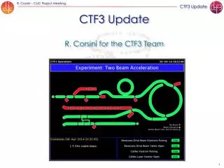
CTF3 BPMs. Agenda. Different types of BPMs Electronics Radiation problems From CTF3 to CLIC. CRM. TL1. DL. CR. TL2. CLEX. C LIC T est F acility 3. A total of 137 BPMs. TL1 & CRM commissioned fall 200 6. Delay Loop: commissioned with beam 2005-2006.


CTF3 BPMs
E N D
Presentation Transcript
CTF3 BPMs IWLC2010 CTF3 BPMs
Agenda Different types of BPMs Electronics Radiation problems From CTF3 to CLIC IWLC2010 CTF3 BPMs
CRM TL1 DL CR TL2 CLEX CLIC Test Facility 3 A total of 137 BPMs TL1 & CRM commissioned fall 2006 Delay Loop: commissioned with beam 2005-2006 Linac: commissioned with beam 2003 - 2004 CR commissioningsince 2007 TL2 and TBTS commissioning started August 2008 IWLC2010 CTF3 BPMs
ElectrostaticPick-up (BPE) Electrode, C~100pF RF contacts Feed-through’s Developed by L. Søby, CERN IWLC2010 CTF3 BPMs
Electrostatic PU (BPE) BPE sum signals Buffer amplifier, RL=1MΩ HT bias Electrodes charging up due to beam halo! IWLC2010 CTF3 BPMs
Current transformer Inductive Pick-Up’s (BPM, BPI, BPS, EuroTeV) Titanium Electrode Ferrite • Robust and well know design (LPI) • Electrodes outside ceramic chamber • Each transformer has one calibration turn. • Provides current measurement. • Many different parts gives limited absolute accuracy • Resolution limited to ~ 50um. IWLC2010 CTF3 BPMs
Inductive pick-up’s (BPM) Developed by M. Gasior, CERN 46 BPM’s installed as from march 2008 IWLC2010 CTF3 BPMs
Developed by A. Stella, Frascati Inductive Pick-up’s (BPI) Current transformer with 30 turns and RL=14Ω 4 electrodes installed on racetrack chamber 52 BPI’s installed as from march 2008 IWLC2010 CTF3 BPMs
EuroTeV Inductive BPM Stdev1PBPM _1.5A= 0.6µm IWLC2010 CTF3 BPMs
Inductive BPS BPM developed by Juan J. Garcia-Garrigos, IFIC Valencia, Spain Electronics by: G. Montero UPC, Barcelona, Spain Noisy and wrong measurements close to PETS IWLC2010 CTF3 BPMs
Button Pick-up’s (BPR) Developed by L. Thorndahl et al. IWLC2010 CTF3 BPMs
Button Pick-up’s (BPR) Button electronics Phase set to maximum. Phase set to minimum IWLC2010 CTF3 BPMs
Button Pick-up’s (BPR) BPR – RF phase monitor Combiner ring path length Simulated signal Combination factor 4 Combination factor 4 with + 5 error Plot by R. Corsini Phase advance per turn (3GHz) IWLC2010 CTF3 BPMs
Button Pick-up’s (BPR) Waveguide electronics RF in Shorter bunches means more power in the WR28 IWLC2010 CTF3 BPMs
Re-entrant Cavity BPM (CALIFES) Developed by M. Loung, C. Simon, Sacley • Re-entrant geometry for a higher frequency separation between the monopole and dipole modes. → Better CMRR • Resolution: ~ 1um (CALIFES ~5um) • Qld= 50 → Time resolution ~ 2-3ns • ID 18mm; Length ~100mm. IWLC2010 CTF3 BPMs 15
Re-entrant cavity BPM electronics Re-entrant Cavity BPM (CALIFES) Only one BPM at a time IWLC2010 CTF3 BPMs
“Standard” acquisition system Acquisition system: Linac, CR Control room Tunnel • Front-end electronics gives improved CMRR. Calibration of position and intensity . • Observation of analogue signals IWLC2010 CTF3 BPMs
LAPP Acquisition system: TL2, CLEX CLEX Gallery Tunnel • Front-end electronics maintained. • Signals digitized in tunnel ☺→Big reduction in cable costs • No analogue signal observation . IWLC2010 CTF3 BPMs
LAPP acquisition system Designed to withstand 300GY. FPGA sensitive part. Communication link died rather quickly due to too high radiation doses. LAPP is developing new front end acquisition system. To be used on each CLIC module not only for BPMs, but for all “clients” IWLC2010 CTF3 BPMs
Calibration IWLC2010 CTF3 BPMs
From CTF3 to CLIC High accuracy and resolution as well as big numbers eliminates inductive BPM’s! If 1% of our BPMs fail we have more than 500 BPMs not working and which must be repaired. IN CTF3 we have had only 2 BPMs failing……. IWLC2010 CTF3 BPMs
Main linac BPM’s (baseline) Main beam BPM Drive beam BPM IWLC2010 CTF3 BPMs
From CTF3 to CLIC • Large scale projects come along very rarely at CERN • SPS LEP 13 years • LEP LHC 19 years • LHC CLIC ? • Experience is unfortunately lost along the way • Few of the LEP BI construction team saw beam in LHC • Similar mistakes were probably made again • Main Points Retained from LHC Experience (1000 BPMs) • Clear functional specifications required very early • Clear project management structure essential from the outset • R&D, design & testing times largely underestimated • Especially true when designing for radiation environments • Standardisation across domains improves effectiveness as a whole • Quality assurance procedures important for large scale production • Host laboratory personnel time to be foreseen for collaborations Slide by R. Jones IWLC2010 CTF3 BPMs
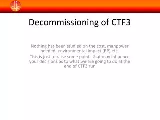
Summery New CLEX and TL2 acquisition system has problems with CPU load, due to too many clients. Work around being looked into by CERN controls group. New calibration GUI is very useful. Noisy signals on BPS close to PETS in TBL line. This is an important information for CLIC and is being looked into. Radiation damage of first generation FE digitizers has shown the need for a robust, simple and standard module acquisition system. CLIC is verydifferent (numbers) from CTF3 and it is very difficult to draw any other conclusions which can be used for CLIC. IWLC2010 CTF3 BPMs