Managing Beam Loss Experience from CTF3 for CLIC Test Facility
Learn about managing beam losses at CTF3 for the CLIC Test Facility, covering transient, steady state, accidental losses, radiation issues, interlocks, RF breakdown kicks, and more. Explore the challenges, strategies, and precautions involved in handling beam power and machine protection.

Managing Beam Loss Experience from CTF3 for CLIC Test Facility
E N D
Presentation Transcript
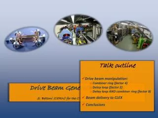
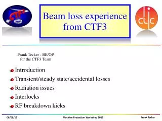
Beam loss experience from CTF3 • Introduction • Transient/steady state/accidental losses • Radiation issues • Interlocks • RF breakdown kicks
CTF 3 – CLIC Test Facility Combiner Ring – 84m Delay Loop – 42m TL1 Laser CLEX TL2 demonstrate CLIC RF power source Drive Beam generation (fully loaded acceleration, bunch frequency multiplication 8x) Test CLIC accelerating structures Test power production structures (PETS) Bunch length chicane 30 GHz “PETS Line” RF deflector Linac Injector 3.5A – 1.2µs150 MeV 28A – 140ns150 MeV 30 GHz test area
Comparison CLIC - CTF3 • CTF3 covers well the CLIC drive beam generation scheme • Still considerable extrapolation to CLIC parameters • Especially total beam power (loss management, machine protection) • CTF3 entry in HHGG: MOSTLY HARMLESS!(Hitch Hiker’s Guide to the Galaxy)
Accidental losses running at higher beam power with up to 50Hz lead to some damage in the past (several kW of beam power) here a vacuum valve (CL.VVS0412)
Accidental losses (2) Damaged a bellow with high dark current from the gun Signs of heating the vacuum chamber in the spectrometer line
Fully loaded linac operation No RF to load RF in Full beam-loading acceleration in traveling wave sections High beam current Most of RF power to the beam “short” structure - low Ohmic losses time E0 Ebeam steady state ~E0 /2 energy The start of the beam pulse receives a different energy gain Steady state after ~cavity fill time tfill t
Loss of transient LINAC DELAY LOOP Transient gets lost mainly at dispersive sections (chicanes, DL,…) Some losses along the linac when collimator wide open (not default) No collimator in the end-of-linac (Frascati) chicane=> gradual losses of the transient in the DL or TL1 CLIC needs proper ‘cleaning’ of the transient (kicker, collimators)
Transient reduction ‘Delayed filling’ of the RF structures can reduce the transient Principle: the travelling wave accelerating structure is only partially filled with RF when the beam passes energy gain can be shaped=> transient efficiently reduced
Steady state beam losses Cleaning chicane Charge losses – Factor 4 BPIs Total loss from cleaning chicane to TBTS ~ 15% BPMs 18th November 2011 T. Persson Also steady state losses along the machine Estimation not precise (different BPM types/electronics)
Radiation issues • => shorter beam pulse for setting up the DL • Remarks: • using existing buildings • radiation limits went down over the years Weak shielding at the entrance door of the DL/CR=> setting up the DL particularly difficult
Radiation issues Weak shielding at the end of the klystron gallery=> setting up the DL/CR/TL2 can be difficult Limits the repetition rate for CTF3 operation
Beam Interlocks • Beam losses are in general not critical • no intra-pulse interlocks • interlocks to reduce beam losses and radiation (mostly software): • RF -> Gun interlock (PLC) • when a klystron is not pulsing, the gun trigger is disabled • Radiation level interlock • when a radiation level is above a certain threshold, the gun is disabled • Beam current interlock • when the beam current falls below a give threshold, the gun is disabled • Vacuum valve interlock (HW) • when a valve in the beam path is closed, no beam is possible • Repetition rate interlock • rate limit based on beam destination
CLEX (CLIC Experimental Area) TL2 Test Beam Line - TBL Two Beam Test Stand - TBTS Probe Beam - CALIFES tests for power production, deceleration and two-beam studies
TBTS beam kick measurements WilfridFaraboliniAndrea Palaia Measured on OTR screen CA.MTV0790 (~4.9 m from the accelerating structure). 2-Gaussian fit on the screen Analysis on ~170 BD events
TBTS beam kick measurements WilfridFaraboliniAndrea Palaia kicks corresponding to transverse momentum between 10 and 40 keV/c(measurements at NLCTA < 30 keV/c) more data with BPMs this year…
Thank you very much! Further questions?