Animation
Animation. Outline. Key frame animation Hierarchical animation Inverse kinematics. Key-framing. One hour of animation on film (24fps) requires 86,400 frames If frames are generated one by one this is an enormous task Key-framing was first used for feature length animation by Walt Disney

Animation
E N D
Presentation Transcript
Outline • Key frame animation • Hierarchical animation • Inverse kinematics
Key-framing • One hour of animation on film (24fps) requires 86,400 frames • If frames are generated one by one this is an enormous task • Key-framing was first used for feature length animation by Walt Disney • ‘Master’ animator draw the key positions • Less experience animators draw in-between frames
Key-framing • Because of its intuitive approach (you put things where you want them at a particular time), this approach is still the most widely used in animation (including 3D computer animation) • In computer animation, the computer generates the in-betweens
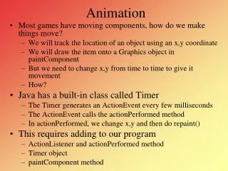
The process on the computer • Objects can be positioned, scaled, etc. and a key frame specified • The object can then be repositioned, scaled, etc. and a second key frame generated later in the animation sequence • The computer will then generate the in-between fames
Example • Position a 1 unit square cube six units along the x-axis at frame 1 and scale it by 6 along the y-axis - create a key frame • Move the cube to the origin (0,0,0) and return its size to 111 - create a key frame at frame 60 • The computer will then generate the 58 in-between frames
The process: interpolation • The computer interpolates the intermediate values from the start and end values • The simplest kind of interpolation is linear interpolation: if you draw a graph of the parameters (e.g. the x coordinate) against time the variation will be in the straight line • But is this enough?
Interpolation (2) • If you have more than two key frames, linear interpolation is likely to yield disjointed motion - how can we solve this? • Recall splines (from the previous modelling discussion): generate smooth curves through a set of given points for generating smooth surfaces • We can use the same maths for generating smooth surfaces
Interpolation (3) • We can use any of the curves used for shape generation for interpolation with different results • Problems can occur with this kind of interpolation • when we move key frames • when we try and make an object remain motionless between movements
Moving key frames • Because the curve remains smooth and continuous, there may be overshoot
Using ‘identical’ key frames • To make an object stay in a position for a length of time it is natural to define the position at a key frame at the start of the period and one at the end • This may (again) lead to overshoot
Overcoming overshoot • To fix these problems, most key frame systems have a method of controlling the way a parameter changes between key frames • These are often called ease controls because they allow you to ‘ease into’ and ‘ease out of’ a position (also ‘slow in’ and ‘slow out’ are used)
Ease out-in Slow ease in Ease in Ease out Slow ease out Ease interpolations Parameter Time
Parameter curves • Another way of controlling the key-framed motion of objects is to actually edit the parameter curve • This is the curve generated by the in-betweening process • We can move the control points (key frames), add and delete them and adjust the curve between the control points
Parameter curve editing in Maya • This is done with the ‘spline controls’ and can be done in the ‘Graph Editor’ • There are different types of behaviour that can be applied through the key frames: spline, linear, clamped, stepped, flat and fixed.
Motion Graphs • Besides offering the tension, continuity and bias control it also allows dragging, deleting and adding key frames • The motion data is separated into ‘channels’: X, Y, Z position, H, P, B angle and X, Y, Z scale • This gives us a useful visual aid to our animation process • Example: bouncing ball…
Hierarchical animation • Why? • Because many real objects are by their nature hierarchical • It allows easy relative movement of objects • It allows easy movement of groups of objects • How? • By modelling the object as a hierarchy and manipulating the hierarchy components appropriately
Hierarchical animation: an example • Suppose we want to animate the EIMC logo • We want the individual letters to ‘tumble’ from different directions and combine to form the logo • We then want the whole logo spin once and move off to the right • The easiest way to do this is to build a hierarchical model with the individual letters as nodes
Example (continued) • The ‘eimc’ can be built as a text object • The letters are then grouped together • Now when the group transformed, each of the letters will also be transformed • Each letter can still be moved independently
Example (continued) • To do the tumbling letters, each letter can be moved and key-framed independently • Once the letters have come together, the group can be key-framed to move the whole logo
Inverse Kinematics • In the previous example, each node (letter) was manipulated separately • This is OK for relatively simple models, but becomes cumbersome for complex models • If you consider a simple human arm, usually you are concerned with the position of the hand more than the rest of the arm • You generally think ‘move my hand there’ rather than ‘rotate the upper arm through A degrees, rotate lower arm through B degrees, rotate wrist through C degrees’
IK continued • The implementation of this is called inverse kinematics • Kinematics is the study of mechanical motion • Inverse refers to the fact that you work backwards from the desired position to work out the positions of the other objects • In the arm example the positions are worked out up the hierarchy from the hand when normally they would be worked out downwards from the shoulder
IK in CA systems • Most modern CA systems (including Maya) support automatic ‘IK’ing • Because many of the hierarchies that are IK’ed resemble chain-like structures they are called IK chains with each node being a link • When the approach is used for human or animal systems, the IK structure is often called a skeleton and the nodes are called bones • The link is called the effector because its ‘effect’ is on the transformations of all the other nodes
IK in CA systems (cont) • Many joints in real systems have limited motion - this can be defined in most CA systems • It is usually possible to combine IK chains into more complex hierarchies (i.e. join together arms, legs, etc. to form a whole body)
IK skeletons and geometry • So far we have just considered the topology of the object not the geometry • For the final animation we need some geometry to be ‘attached’ to each IK node • There are two common ways to do this...
Attaching geometry to nodes • The simplest method is just to attach a geometric shape to each node • E.g. cylinders to simulate fingers, etc. • This is simple, but not very effective for realistic modelling • Discontinuities will occur at joints when large rotation angles are used
Attaching geometry to nodes (2) • The second option is to cover the skeleton in one continuous surface and deform this surface when the skeleton is moved • This is called envelope or skeleton deformation • The skeleton acts like a magnet, attracting points on the envelope when the skeleton is moved • This can be very effective in producing realistic shapes, but there is a problem…
Problem with skeleton deformation • There can be unnatural deformations at the joints of the skeleton • Some systems allow you to control the local deformation of the surface around joints to overcome this.
Practical IK • Can use IK goalsfor objects or bones – goals are the places you want your IK effectors to move to • You can use hierarchies of objects or bones that distort the geometry around them as in skeleton deformation
IK goals • IK goals are objects that the effector will try and move towards • These can be real objects, or more usually objects that won’t appear in the final rendered scene • If the effector cannot reach the object (due to the fact that it is linked to the other parts of the chain) it moves as close to the goal as it can
IK goals (cont) • You can have multiple goals for different effectors in the chain (e.g. the hand and the elbow may have their goals) • You can also ‘lock’ parts of the chain so they do not rotate • You can stop the parts of the chain rotating about particular axis by deselecting these on the mouse action buttons
IK goals (cont) • You can also specify through what angle the link can rotate through by setting this on the item properties panel • The final parameter you can alter is the ‘stiffness’ of the link • This specifies how much a given link will rotate relative to other links in the chain