Download

1 / 38
380 likes | 477 Vues
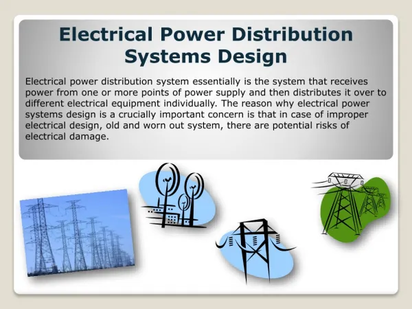
This industrial design application focuses on efficient power distribution over large distances, aiming to eliminate downtime, protect systems, and ensure system voltage stability. The project addresses unique challenges of large loads spread over geographically dispersed locations with a focus on robust construction methods, environmental considerations, and effective electrical constraints. The system incorporates smart solutions for starting loads, managing overcurrent protection, and incorporating capacitors for power factor correction. Lightning protection measures and effective grounding systems are crucial for system reliability.

E N D
Industrial Design Application for Power Distribution over Extra-Long Distances Or Lots of Wire Little Vd Robert A Durham, PE New Dominion, LLC Tulsa, OK Marcus O Durham, PhD, PE THEWAY Corp Tulsa, OK
Introduction • Typical petrochemical installations: Geographically confined Large loads • Utility installations: Geographically dispersed Distributed loads • Large loads over large distance cause unique problems
IntroductionGoals • Downtime eliminated • Protection system isolates faults • Total system voltage > 95% • Contingency is bi-directional feed • Adequate Ampacity to prevent sags
Loads • Primary loads • 150 – 400 Hp, 2400 VAC • 2 pole, low inertia • Steep speed-torque curve • Centrifugal pumps • Eff 80%, pf 78%
Loads Secondary Loads • 1000 Hp, 2400VAC • 4 pole, induction machines • Reciprocating compressors
LoadsStarting • Primary Loads (150 – 400 Hp) • Generally started across the line • Some use VFD • Inherent robustness of system adequate
LoadsStarting • Secondary Loads (1000 hp) • Vd caused by starting trips primary load • Need soft start – 60% FLA
Geography • System spread: over 900 square miles • Main trunk line: 25 miles in length • Radial lines: 1 – 12 miles long • Each radial: 1 – 5 MW
Design Philosophy • Difference between utility & industrial - purely a matter of economics • Utility: Downtime = loss of electric sales • Industrial: Downtime = loss of production sales • Damage to production may be unrecoverable • Industrial has much larger risk
Construction Management • Emphasis on elimination of maintenance • Contractors used on day work basis
Environmental Controls • ROW clearing • 60’ - 100’ wide • leave root balls for erosion control • treat with herbicide • 95% of recovered product is waste • Extensive load shedding and motor control used to ensure responsible disposal
Meteorological Considerations • Temperature range: –23C to 47C • Thunderstorms: 55 isoceraunic days • Ice: “Heavy” ice loading area • Wind: Basic winds 80 MPH • Severe: Heart of Tornado Alley • Seismic: Occasional earthquake • No applicable industry standards • Build above utility standards
Table 1 Line Construction Practices Conductor Industrial Utility Size (ACSR) Span Span 477 kcmil 64 m (210 ft) 76 m (250 ft) #4/0 69 m (225 ft) 76 m (250 ft) #1/0 69 m (225 ft) 90 m (295 ft) #2 76 m (250 ft) 90 m (295 ft) Add 4 poles / mile (1.63 km)
Results of Philosophy • Recent winter storm • Severe icing in region • Some areas w/o utility for 30 days • The system discussed here • single incidence of blown fuses • no line on ground
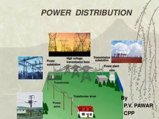
Supply • Most loads this size served from transmission • Limited number of 69 /138 kV lines in area • Supply taken at distribution levels
Supply • Supply taken at distribution levels • Many areas served from REC lines • Some dedicated 138/25kV subs • At dedicated subs, voltage as high as 120% assists with voltage conditions
Electrical Constraints Wire size based on ampacity- Sag Here, voltage drop is main concern Low power factor contributes Main trunk line : 477 ACSR Main branch feeders: 4/0 ACSR Individual load service: #2 ACSR
Capacitors • With no correction – system at 80% pf • Standard – place caps on lines
Capacitors • Extensive load shedding system can trip large quantities of load • Resulting excessively leading pf can damage equipment, cause trips • Must switch caps with load shed • Place oil reclosers or sectionalizers at each 25kV cap bank
Capacitors - Options • Place medium voltage caps at motors • Automatically switch w/ load • Nearest to load • Can downsize transformers and fuses • Cost less than oil switches
Overcurrent Protection • Two unique systems • Protect motor & transformer (load point) • Protect system from cascading faults
Overcurrent Protection • Load points protected with fused cutouts • Fuse links sized tightly to avoid extra trips • Use high speed (X speed) fuse links
Overcurrent ProtectionMain Line Cutouts • High risk of single phasing motors • High rating of fuses makes coordination with utility difficult • Electric storms cause unacceptable # of outages due to arrestor operation • Outages require electrician to restore power = excessive downtime
Overcurrent ProtectionMain Line Reclosers • Oil reclosers placed at utility supply point and each main branch feeder (2MW or greater load) • Oil reclosers placed along trunk every 10 MW
Overcurrent ProtectionMain Line Reclosers • Main line reclosers use processor relays • Branch reclosers can use • plug-setting type relays • processor when available
Lightning • Lightning is a major concern in this area • 55 isoceraunic days per year • odds of induced or direct strike high • Lightning arrestors • placed every 1500 – 1700 feet • Excellent ground system is imperative
Effective Grounding Multi-point ground required Personnel safety Equipment protection Length of system #1 factor L of ground wire length Long distance = high Z • Single point ground Does Not Exist
Computer Modeling Selection • Cost - $10,000 • Cost - Approximately two weeks engineering time • Numerous products on the market • Two are usable for this type design • One was selected based on overhead line modeling capabilities
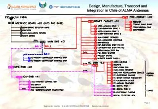
Computer ModelingProcedures • Build single motor model for each service point • Create motor subsystem consisting of motor, transformer, switches, etc • Combine several subsystems on a sub-trunk feeder
Computer ModelingProcedures • Tie sub-trunk feeders to main trunk line • Add detail for protection devices, fuses, switches, capacitor, microprocessor relays, motor protection devices
MOTOR1 184 HP FUSE101 CONT5 FUSE12 CAP27 120 kvar T6 225 kVA SCHEMATICMOTOR MODEL FUSE13
Computer ModelingUses • Original model created as design tool before any construction • Allowed alternatives for conductor size, lengths, protection • Used model during construction for communication with crews
Computer ModelingUses • Refined model for operations – voltage drop, current, power factor • Updated model for system upgrades • Recent upgrade netted 8% reduction in electric bill – 6 month payout
Review Goals • Downtime eliminated • Protection system isolates faults • Total system voltage > 95% • Contingency is bi-directional feed • Adequate Ampacity to prevent sags
Computer modelingSystem Results • Under normal conditions voltage drop is 8% • Supply voltages at 115% allow for continuous operation under contingency • Advanced coordination of protection allowed advanced devices with little on-site prep • Properly coordinated protection shields equipment w/o unnecessary downtime
Conclusions • Uncommon: spread out industrial system • Semi-utility design + uniquely industrial ops • Enhanced specs, > cost, more reliable • w/o computer, complex system impossible • Design, construction, operations, mgt. • One engineer
Conclusion • ConclusivelyWith the aid of modern tools, a system can be designed that * can meet industrial needs * in a utility environment * with environmental astuteness * by a single engineer