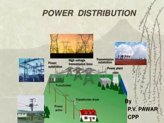
POWER DISTRIBUTION
Dive into power distribution concepts by P.V. Pawar, exploring power factor, apparent power, single-phase vs. three-phase systems, transformer principles, and advantages of a three-phase system. Learn about power system operation, voltage fluctuation, synchronization, and billing structures in CPP operation with the MSEB grid.

POWER DISTRIBUTION
E N D
Presentation Transcript
POWER DISTRIBUTION By P.V. PAWAR CPP
POWER Power factor : Power factor is the ratio between the KW (actual power) and the KVA drawn by an electrical load. P.F. = KW VI Cos phi -------- = -------------- = Cos phi KVA VI Apparent power : It is the product of r.m.s. value of voltage and r.m.s. value of current. Its unit is VA, KVA, MVA KVA - Apparent power or Produced power = V X I Causes of low factor1) Induction motors. 2) Power transformers, welding transformers. 3) Industrial heating furnaces 4) Lighting loads through ballasts. Effects of low factors : 1) Loss of electrical energy, I2Rt losses in transmission line. 2) Poor voltage regulation. 3) Poor use of electrical equipment ratings.
SINGLE PHASE / THREE PHASE Two methods of interconnection – 1) Star connection or Y connection. 2) Delta connection or Mesh connection. A single phase alternator has only one armature wdg. And hence they produce a single alternating voltage and current. If the armature windings are increased to 3, then it will produce 3 independent voltage waves. A three phase alternator has three independent armature windings which are 120 electrical degrees apart.
STAR / DELTA Star Connection – Similar ends are connected N is called star point or Neutral point. A conductor can be connected to neutral point; it is called as neutral conductor. Star connected system may be 3 phase 3 wire system or 3 phase 4 wire system as per the loading requirements. Here, line current (IL) = phase current (Iph) (contd) Line voltage (VL) = Sq Rt 3 V ph Power = Sq Rt 3 VL x IL x cos phi
STAR / DELTA Delta connection : Here dissimilar ends are connected, i.e. starting end of one phase is connected to finishing end of other phase. It is a 3 phase 3 wire system. Here, VL = Vph IL = Sq Rt 3 Iph Power = Sq Rt 3 VL x IL x Cos phi Hence in both the cases power = Sq Rt 3 VL x IL x Cos phi Advantage of 3 phase system over single phase system : For the same size a three phase a.c. machine has higher KVA capacity, hence is more economical than single phase machine. Small loads like lighting loads, fractional KW motors are single phase loads. Large motors, transformers, machines are 3 phase loads.
Transformer It works on the principle of Electromagnetic Induction Ns Vs Ip Transformation ratio =----- = ----- = ----- = K Np Vp Is Transformer is a device/machine, that transfers electrical energy from one electrical ckt. to another electrical circuit through the medium of magnetic flux and without change in frequency. It decreases or increases the voltage with corresponding decrease of currents keeping the power same. Transformer is a static device, there is no moving part, so efficiency is the highest amongst all machines and maintenance and supervision is negligible.
Transformer • Uses of Transformer - 1) Backbone of ac transmission 2) CT/PT for metering/protection. 3) For isolating dc from AC • Step up transformer - Secondary voltage is greater than primary voltage. • Step down transformer- Secondary voltage is less than primary voltage.
POWER SYSTEM For transmitting large power over large distances through transmission lines voltage level is increased for less power losses. All transmission and distribution system are 3-phase system. Transmission lines and feeders are 3 phase 3 wire circuit while distribution lines are 3 phase 4 wire circuit. Transmission lines are generally overhead while distribution system can be overhead or underground as per the locality. Transmission Levels ( 66 KV, 132 KV, 220KV, 400KV, 765 KV)– (RMS) Distribution Level – (400V, 3.3 KV, 6.6KV, 11KV, 33 KV) 50 hz (RMS)
SYNCHRONISATION When 2 power sources are to be connected in parallel (together) , it is required to be synchronised. To satisfy synchronisation condition Both Voltages should be equal. Frequency should be same. Phase angle should be less than 15 degrees.
CPP operation with MSEB GRID Power triangle Power factor = Cos ¢ = KW / KVA
CPP OPERATION WITH MSEB GRID While CPP is synchronized with MSEB GRID following 4 quadrant shows possible conditions in which power flow can happen Reactive power import (KVAR) Q2 Q1 Active power export (KW) Active power import (KW) Q3 Q4 Reactive power export (KVAR)
PRESENT OPERATING CONDITIONS For the purpose of billing, following two quadrants are applicable since total KVA import is recorded in this region only. Reactive power import (KVAR) Q1 Active power import (KW) Q4 Reactive power export (KVAR)
MSEB BILL STRUCTURE KWH = Total active power imported (Quantity on X axis) KVAH = [ KWH2 + (RKVAH Q1 + RKVAH Q4)2 ] RKVAH lag = Total reactive power imported (Quantity on + Y axis) KVA (MD) = Average KVA supplied during thirty minutes period of maximum use
MSEB BILL STRUCTURE • Billed Demand ( Which ever is higher of the following) • Actual KVA (MD) recorded between 06.00 to 22.00 for the month. • 50% of contract demand (17600 KVA is contract Demand) • 75% of maximum MD recorded in preceding 11 months. PF penalty / Incentive : PF < 0.9 Penalty 0.9<=PF<=0.95 No penalty / incentive PF > 0.95 Incentive Average Power Factor Avg PF = KWH / KVAH Assessed Power Factor Assessed PF = cos [ tan-1(RKVAH (lag) / KWH) ]
Reactive power export (RKVAH lead) Q4 Total KVAH Reactive power import (RKVAH lag) Q1 ¢ Active power import (KWH) WHY ASSESSED PF ? Assessed PF = cos [ tan-1(RKVAH (lag) / KWH) ] Avg PF = KWH / Total KVAH
MSEB Tariff & Billing • Fixed Part • (Demand charges in Rs/KVA) This is called Demand charges. A consumer gets into contract with MSEB for specified MVA demand. The Electricity board should always have a provision for supplying the contracted demand to the consumer. Therefore, MSEB charges a fixed amount per MVA (called as billing demand). The consumer has to pay this amount whether he utilises power or not.
MSEB Tariff & Billing • Variable Part • (Energy charges in Rs/kwh) • This is called Energy charge. Depending upon the number of units (KWH) consumed by the consumer, one has to pay for it (Rs./KWH). • Various levies & Duties are applicable to Fixed and Variable Parts.
Constituents of MSEB bill • Demand Charges : Charged on billing demand and payable @ rate of Rs 3.5 lacs per MVA • Additional supply charge leviable on 42% of energy consumed at Rs 5.15/ unit • Energy Charge : Charge for the number of units consumed in a billing period ( month) and expressed in Rs./KWH
Constituents of MSEB bill(Contd.) • Fuel & Other Cost Adjustment Clause (FOCA): Energy charges prescribed for the various classes of consumers are based on an average cost of fuel which includes expanses related to coal, furnace oil, L.D. oil or fuels consumed in the Terminal or Gas Turbine Stations. • Electricity Duty : Electricity Duty is collected in accordance with the rates prescribed by Government from time to time.
PF Penal Charges : • A penal charges is levied to the consumer whenever the average power factor is less than 0.9, at the rate of 1% on their monthly bill exclusive of fuel adjustment charge, and electricity duty for each 1% fall in the power factor below 0.90
BILL CALCULATIONS Fixed part or Demand Charges : • Contract Demand (CD) = 17,600 KVA or 17.6 MVA • Minimum Demand (MD) = 50% of CD = 8.8 MVA • Actual Demand (AD) = as per the actual readings. • Demand charges are calculated for the highest of the values as per the following conditions. • Condition 1 - AD between 6.00 hrs to 22.00 hrs. • Condition 2 - 75% of the max. A.D. of last 11 months. • Condition 3 - MD • Present demand charge is Rs.350/KVA/Month.
Variable part or Energy charges ShiftTime Rate A 22.00- 06.00 (-85) Paise/unit B 06.00- 09.00 Normal rate Rs.2.15/unit 12.00-18.00 C 09.00-12.00 (+ 80) paise/unit D 18.00-22.00 (+115) paise/unit
LOAD SHEDDING SCHEMES IN IPCL-MGCC • System Generated load shedding • Hard wired load shedding • This is as Frequency based load shedding. • Entire 18 MW load selected, will be shedded at a single stroke. • ECS load shedding
HARD WIRED DEMAND BASED LOAD SHEDDING Three blocks of load are shed one after the other if the import exceeds the stipulated amount, by the operator manually. BLOCK-I : Township feeder 1 & 2 IWWTP .kv & PCC feeders PP Extruder LLDPE Extruder (1+2+3) BLOCK-II : Ethyl BOG Compressor(1+2) LDPE Extruder LDPE hyper compressor LDPE Comb. Compressor BLOCK-III : LLDPE Recycle Compressor(1+2) N2/O2 Demag. Compressor W&C feeder 2
HARD WIRED DEMAND BASED LOAD SHEDDING Different amounts of load are shed at different times of the day according to our contract with the state grid. a) For power import in A or B shift (0600 hrs to 2200 hrs) Upto 9.0 MW (11.7 MVA) No action 9-16 MW BLOCK-I 16-23 MW BLOCK-I&II >23 MW BLOCK-I,II&III b) For power import in C shift ( 2200 hrs to 0600 hrs , next day) Upto 14 MW No action 14-21 MW BLOCK-I 21-28 MW BLOCK-I&II >28 MW BLOCK-I,II& III
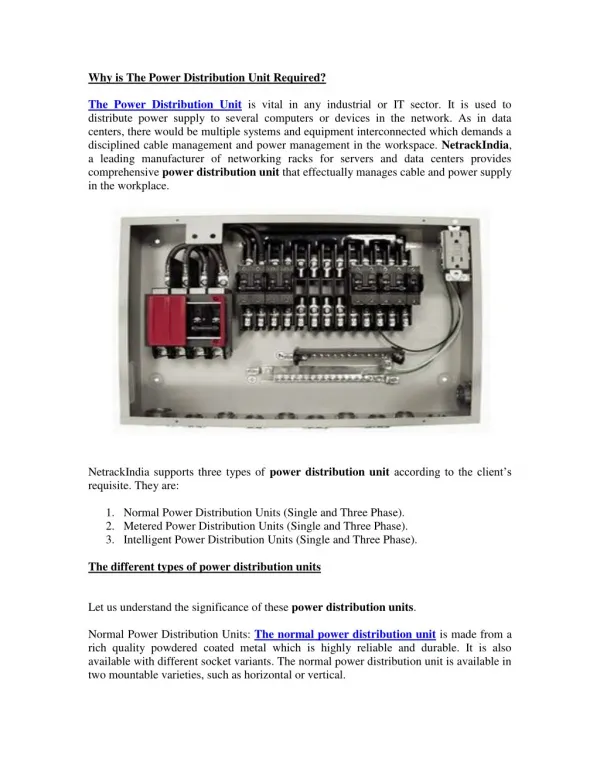
POWER DISTRIBUTION. • CPP 11 KV Bus is divided into 6 Bus sections namely 1A, 1B, 1C, 2A, 2B and 2C. • Limiting Series Reactors, connecting buses 2B-2C (Reactor 1) and buses 1B-1C (Reactor 2). These • series reactors have a rating of 11kV, 2000A. • Each Bus section has a dedicated Power Source.
POWER DISTRIBUTION • 11KV feeders are provided to each Plant from this CPP bus. • The Plants receives power through 2 independent 11 KV feeders from CPP. Bus 1A & 2A have MSEB source; whereas theremaining4buses each have 1 Generator.
POWER DISTRIBUTION Each feeder is capable to carry 100% Load. • One Plant feeder is connected to Bus 1A-1B-1C and second to Bus 2C-2B-2A. • There is at least 1 Plant feeder on MSEB source bus 1A or 2A.
POWER DISTRIBUTION • For transferring load from 1 incomer to other incomer bus coupler is used. Each Plant has 2 incomers and a bus coupler arrangement. Normally both incomers to plant are ON with Bus coupler OFF. • There is also Auto power transfer schemes, which allows power to be transferred from unhealthy incomer to healthy incomer.
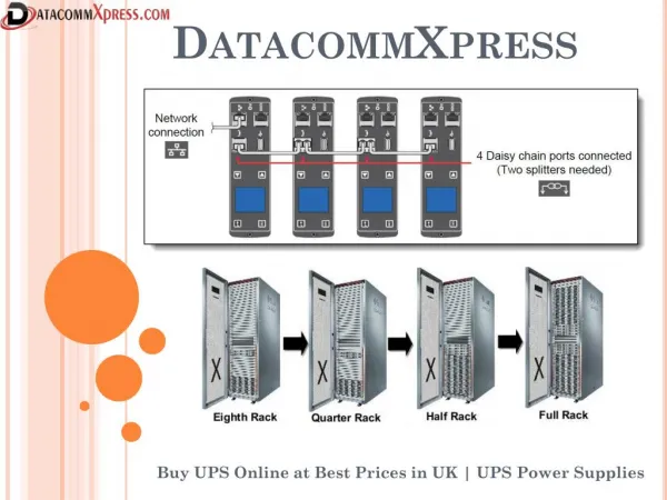
Distribution Philosophy • NC receives power from MSEB through 2 grid transformers. • The generation and CPP to plant distribution network is at 11KV. • 11 KV armoured cables are laid between CPP to each plant mostly through underground tunnels or laid underground. • Each plant feeder is capable of carrying 100% plant load. • 11KV power is received by plant to a 11KV Siemens switch board, which consists of vacuum circuit breakers. VCB
Distribution Philosophy (Contd.) • 3 nos. of 11KV motors, one each in LDPE, LLDPE and PP plants are connected to respective plant 11KV board. • All these motors are direct-on-line starting motors. • For all other HT motors, a separate 6.6 KV switch board is installed. • 6.6 KV switch board receives power from 11 KV switch board in plant through 2 nos. of 11/6.6 KV transformer. • Each 11KV/6.6KV transformer can carry 100% load. • For LT (415V) power supply requirement, Power control centers (PCC) boards are installed.
Distribution Philosophy (Contd.) • Each PCC receives power power from 11KV switch board in plant through 2 nos. of 11KV/433V transformer and each transformer can carry 100% PCC load. • The primary of transformers are connected through cables, whereas secondary of transformers may be a bus duct or cable depending upon load. • All transformers have primary winding in Delta & secondary in Star. • All motors above 160 KW are HT motors. • Motors rating of 55KW and above are Breaker controlled motors.
Distribution Philosophy(Contd.) • Most of the motors below 55KW are fed through Motor Control Centers( MCC ) which receive power from PCC. • Motors below 55KW are contactor controlled motors. • The internal plant load network connections are through armoured cables laid on cable trays. • Separate power &control cables are used. • The largest size of LT cable is 300 sq. mm. • Power cables upto 300 sq. mm. are 3 core or 3 ½ core. • Power cables greater than 300 sq.mm. single core cables e.g. 1C * 400 sq.mm., 1C * 1000 sq.mm.
Distribution Philosophy(Contd.) • The emergency board may have a D.G. set connected to it. All emergency loads like UPS, battery charger etc. are connected to emergency boards. All emergency boards are LT boards. • For lighting distribution, dedicated dry type transformers are used, as the network is single phase. • Each lighting distribution boards(L.D.B) is provided with ELCB. • For street lighting 1st pole is connected to ‘R’ phase, 2nd pole to ‘Y ‘ phase, 3rd to ‘B’ phase, 4th again to ‘R’ phase and so on.
ELECTRICAL CONTROL SYSTEM (ECS) •Supplied by M/S Westinghouse Process Control Division, USA. •Commissioned in 1989-90 •Electrical control system is a DCS used for MGCC electrical network monitoring & control functions. • •16 redundant controller with I/Os at various substations
ELECTRICAL CONTROL SYSTEM (ECS) •2 Operator & 1 Engineer station at CPP C/R. •2 Historian at CPP C/R. •Redundant MicroVAX computer at CPP C/R. •Co-axial cable network as data highway. •Repeater at GC and IOP sub station.
ECS APPLICATION PROGRAMS Data acquisition from substations: •Live data is updated maximum every second, converted to engineering unit and limit checked. •Electrical parameters monitored are: current, voltage, active power, reactive power, breaker on/off, switch selection from various substation, etc. Alarm function.: •Live data is checked against set limit, incremental/decremental limit to generate an alarm.
ECS APPLICATION PROGRAMS Log generation: •Alarms & status change with date and time is logged on a dedicated printer at one of the operator consoles to facilitate analysis after any event. Parameter monitoring/trending: •Real time monitoring of parameters is available on operator console in a trend format of 10 & 60 minutes time span. •Past trend of configured parameter is available for time span of one second to 60 days.
ECS APPLICATION PROGRAMS Tie line control: •This application is used when CPP is operating in parallel with MSEB. •It controls power import/export from/to MSEB by sharing the loads on the in plant running generators Unit load control VAR control of generator Reactive power adjustment on generator is done through a single screen having real time data of reactive power of the entire system.
ECS APPLICATION PROGRAMS •Daily/Monthly energy accounting of plants & equipments is done by resident algorithms. Contingency analysis and load shedding: Energy generation/consumption recording for all plants: Switch board bus transfer scheme:
EMERGENCY POWER Emergency power system may also be defined as Independent reserve source of electrical energy On failure or outage of normal source (black out) automatically provides reliable electric power Black start of a gas turbine generator for restoration of power. Emergency D.G. set installed for back-up supply to GT auxiliaries.
EMERGENCY POWER • AC - UPS (Battery back up- 1 hour, CPP –30 min) - DG Set DC - Battery charger (Battery back up) Emergency lighting (AC/DC) - Plant lighting (field/C.R./S.S.) - Indicating lamps - Protection supply
Battery Charger in CPP 110 V Battery Charger: There is a dedicated battery charger for 110 V DC instrumentation power supply with 2 battery backups and 2 Parallel redundant Rectifiers. 125 V Battery Charger: Each Gas turbine has a dedicated 125V DC Battery charger along with battery back up for supplying control power to GTGs. 220 V Battery Charger: There is a dedicated battery charger for 220 V DC power supply for Electrical Switchgear control with 2 battery backups and 2 Parallel redundant Rectifiers. All the Battery Banks in CPP are of Nickel Cadmium type.
PROTECTION SYSTEMfor electrical faults • Grid islanding is done through =>Under frequency, rate of fall and rise of frequency =>Under voltage => Directional over current and earth fault. Generators have a comprehensive protection system to cover all types of electrical faults. • All 220 KV and 11KV buses are protected by Bus differential protection. • All 11 KV cables to and from CPP are protected by pilot wire cable differential protection.
PROTECTION SYSTEMfor electrical faults • All breaker controlled motors have comprehensive motor protection relay. • All motors above 1MW rating have motor differential protection. All 5MVA and above rating transformers have transformer differential protection. • All feeders have over current and earth fault protection.
Power Distribution & Philosophy THANK YOU