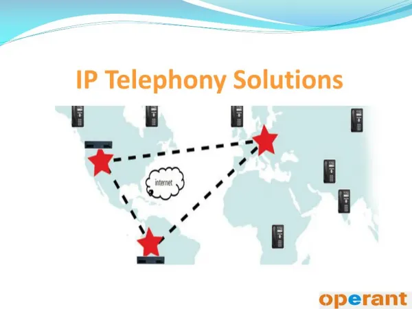
IP Telephony
IP Telephony. Read Chapter 4, 6.5, 9.3. Chapter Outline. Exercise (Key elements to transport voice over Internet) The public switched telephone network An historic line introduction IP telephony Overview (key elements) From sound to bits (Speech coders)

IP Telephony
E N D
Presentation Transcript
IP Telephony Read Chapter 4, 6.5, 9.3
Chapter Outline • Exercise (Key elements to transport voice over Internet) • The public switched telephone network • An historic line introduction • IP telephony • Overview (key elements) • From sound to bits (Speech coders) • Transport Layer for real time application • Helper protocols IP Telephony
The Public Switched Telephone Network Tanenbaum 2.5
Sound to Electrical Signal • Sound waves impact an electrical property of a component in a circuit (Source How Stuff Works): • Carbon microphones - The oldest and simplest microphone uses carbon dust. This is the technology used in the first telephones and is still used in some telephones today. The carbon dust has a thin metal or plastic diaphragm on one side. As sound waves hit the diaphragm, they compress the carbon dust, which changes its resistance. By running a current through the carbon, the changing resistance changes the amount of current that flows. • Dynamic microphones - A dynamic microphone takes advantage of electromagnet effects. When a magnet moves past a wire (or coil of wire), the magnet induces current to flow in the wire. In a dynamic microphone, the diaphragm moves either a magnet or a coil when sound waves hit the diaphragm, and the movement creates a small current. • Ribbon microphones - In a ribbon microphone, a thin ribbon is suspended in a magnetic field. Sound waves move the ribbon which changes the current flowing through it. • Condenser microphones - A condenser microphone is essentially a capacitor, with one plate of the capacitor moving in response to sound waves. The movement changes the capacitance of the capacitor, and these changes are amplified to create a measurable signal. Condenser microphones usually need a small battery to provide a voltage across the capacitor. • Crystal microphones - Certain crystals change their electrical properties as they change shape. By attaching a diaphragm to a crystal, the crystal will create a signal when sound waves hit the diaphragm. IP Telephony
Sound to Electrical SignalExample • High school electromagnetic: a variation of electromagnetic field induces a current. Induced current IP Telephony
Key Contribution of Bell • a) A wire can transmit multiple frequencies • b) Sound is composed of waves (frequencies) • Given a) and b), we can send voice over wires IP Telephony
Bell’s Initial system IP Telephony
Bell’s Luck: Offer Switching Service IP Telephony
What Has Changed Since? • Switching, key events • Strowger (until late 80’s) • Digital switches • Terminal always dumb • Huge complexity in the network IP Telephony
The Telephone System Toll office (We may have other levels of hierarchy…) Phone Local Loop End office IP Telephony
The Telephone System • Local loop • analog, twisted pair • One per user • Low bandwidth • Inter switches trunks • digital, fiber • High bandwidth • Shared IP Telephony
Trunks: transporting many conversations on the same “wire” • Frequency Division Multiplexing • Wavelength Division Multiplexing (Fiber) • Time Division Multiplexing IP Telephony
Frequency Division Multiplexing • Let the signals we need to transmit working in D frequency. • All signals are raised in frequency by n.D’ such that D’ > D. The extra is called guard band. • All signals are added IP Telephony
Frequency Division Multiplexing(Example) • The phone voice is limited to D=3000 Hz frequency. • All signals are raised in frequency by n.D’ with D’=4000 Hz (two 500Hz guard band) • All signals are added IP Telephony
Frequency Division Multiplexing 4000Hz 1 group (60 to 108KHz) 12 1 super group 5 1 mastergroup 5 IP Telephony
Time Division Multiplexing • Works only for digital signals • Allocate time slots to every signal • Each signal has the exclusive use of the line for a given time slot IP Telephony
TDM (Example) 1200 bits/s 2400 bits/s 1200 bits/s IP Telephony
How to Convert an Analog Signal Into Digital Signal? (Principles, then Technology) • Signal sampling frequency • Nyquist theorem (sets lower bound) • “Phone” voice within 300 to 3400 Hz • Quantization: • Number of levels • Distribution of levels IP Telephony
Quantization • Number of levels: • 128 (7 bits) or 256 (8 bits) • Distribution of levels: • Uniform (Higher error for whisperers than shouters) • Non uniform: (Put more levels on low signals) IP Telephony
Data Rate Requirements • Sampling frequency and Quantization yields data rate. • Goal: minimize data rate requirement while maintainin good quality of speech • Play on coding techniques IP Telephony
Coding Techniques • Waveform codec: no assumption on source of signal • Sourcecodec: source is assumed • Either exploit properties of signal • Or model the source • Hybrid codec: combine above IP Telephony
Performance of Codec Types IP Telephony
Uniform Quantization Level Max Min 16 32 48 64 80 96 112 128 IP Telephony
Non Uniform Quantization:A-Law and m-Law IP Telephony
Difference A-Law / m-Law A-Law m-Law IP Telephony
Example: PCM for Time Multiplexing • A codec digitalizes 24 voice channels (7 bits per sample) • How many bits does this represent in one sampling time unit ? • Assuming an extra bit per sample, what should be the data rate to transport all 24 samples + 1 framing bit IP Telephony
PCM : Transporting Digital Voice • A codec digitalizes 24 voice channels • How many bits does this represent in one sampling time unit ? • Assuming an extra bit, what should be the data rate to transport all 24 samples + 1 bit IP Telephony
Compressing Data • Delta Encoding • Send periodically a full sample • Between full samples, send only difference with previous sample sent • Predictive encoding • Similar to Delta encoding, except that the difference with the predicted value of current sample is sent. IP Telephony
Example: Adaptive Differential PCM IP Telephony
Codecs Performance IP Telephony
HLR M VLR SS7 LLC Relay SCCP TCP/UDP TCP/UDP BSSGP BSSGP BSSGP SCCP PSTN PLC Network Se. MTP3 Network Se. IP/X.25 Network Se. MTP3 MAC O 922 Core O 922 Core L2 L2 MTP2 O 922 Core MTP2 BSC GSM RF PHY PHY MTP1 MTP1 PHY PHY PHY MAP Packet Switched Network GTP TCAP SGSN GGSN Application IP/X.25 SNDCP LLC PLC MAC GSM RF GMM/SM MAP GTP TCAP 2.5G Flash Overview Internet IP Telephony
Example: GSM Architecture/Evolution • Quite similar to IS-41 standard presented in the “Location management” lecture • We find the same key elements: Base stations, base stations controller, mobile switching centers, HLRs, VLRs, PSTN… IP Telephony
GSM Radio Subsystem • Available spectrum for GSM: 25 MHz=[890MHz-915MHz] Base station Reverse link : Mobile 25 MHz=[935MHz-960MHz] Base station Forward link : Mobile IP Telephony
GSM Uses FDMA…. • Each link (forward and reverse) is divided in bands of 200kHz • ARFCN (Absolute Radio Frequency Channel Number) denotes a pair or reverse and forward link ARFCN 0 1 2 3 4 5 6 …………………………………n IP Telephony
And TDMA • Each ARFCN is shared in TIME by up to 8 mobile terminals (Slot 0 mostly used for control) 4.615 ms One FRAME With 8 slots 0 1 2 3 4 5 6 7 156.25 bits IP Telephony
Traffic Channels • Traffic Channels (TCH): • Full rate • Speech (13 Kbps) • Data with 3 rates (9600,4800, and 2400bps) • Half rate • Speech (6.5 kbps ) • Data (4800 and 2400 bps) IP Telephony
2G TO 3G Systems Read : http://www.site.uottawa.ca/~dimitris/wp_3g.pdf (“Third Generation (3G) Wireless White Paper”) IP Telephony
GPRS : GSM towards UMTS • GPRS provides service on top of two technologies: • GSM • Internet (or other data networks such as X.25) • Basically, how can GPRS offer higher data rates than GSM? (While on top of GSM) IP Telephony
GPRS • Two major components • Change of MAC on the wireless link to use multiple slots (Multiple technologies ) • Open a gateway to Internet right after basestation IP Telephony
Conclusion • Adding data to voice appears to be: • Cumbersome • Complex • Expensive IP Telephony
Alternative ? ALL IP Based Data and Voice Networks
ALL IP Networks • Data (Known) • Voice: • Enable end point to use IP • Time requirements (delay, jitter) • Provide some guarantees (e.g., bandwidth, packet loss) • Enable mobility IP Telephony
Addressing Voice Requirements • Endpoint: • Application Layer (signalling+encode voice efficiently) • Transport Layer (reliability + timing information) • Point to point: • Network layer (QoS guarantees) • Link Layer • Physical layer IP Telephony
Application Layer • Establish/tear down call sessions (H.323 or SIP) • Captures/plays back voice • Encode voice (codecs) • Adapt encoding based on transport feedback (timing, packet loss stats…) • Provides reliability (as needed) IP Telephony
UDP TCP IP Transport Layer (1) • TCP: reliable but congestion mechanisms unfit for real-time (regular/smooth) traffic • UDP: no recovery mechanism, essentially an encapsulation mechanism for (non root) users to generate packets on network IP Telephony
UDP TCP IP Transport Layer (2) • Real-Time Transport Protocol (RTP) • Sequencing (but no reliability per say) • Timestamping • Payload type (type of codecs used) • RTP Control Protocol (RTCP) • Monitor of an RTP session quality (delay, jitter, packet loss..) Audio Codecs RTP RTCP IP Telephony
Network Layer • IP: best effort only service • Just over provision your links- • Fine tuning: • RSVP • Diffserv • MPLS IP Telephony
Resource Reservation Protocol(RSVP, RFC 2205) • A source initiates a session description along a path (of routers) • Along the path, routers establish a path state for this session • Receiver initiates a reservation message along the reverse path • Routers reserve the necessary resources for the requested service. IP Telephony
DiffServ (RFCs 2474 and 2475) • Based on Shenker et. al ’s paper (TO READ) in SIGCOMM’98 (Core-Stateless Fair Queueing:…) • Architecture composed of two levels of routers: • Edge routers • Core couters IP Telephony
Core-Stateless Fair Queueing • Edge routers: • Measure different characteristics of traffic • Mark packets according to measurements • Core routers • Assign queue delay • Assign packet loss rate IP Telephony