Capacitors and Inductors
Capacitors and Inductors. Chapter 6. Chap. 6, Capacitors and Inductors. Introduction Capacitors Series and Parallel Capacitors Inductors Series and Parallel Inductors. 6.1 Introduction. Resistor: a passive element which dissipates energy only

Capacitors and Inductors
E N D
Presentation Transcript
Capacitors and Inductors Chapter 6
Chap. 6, Capacitors and Inductors • Introduction • Capacitors • Series and Parallel Capacitors • Inductors • Series and Parallel Inductors
6.1 Introduction • Resistor: a passive element which dissipates energy only • Two important passive linear circuit elements: • Capacitor • Inductor • Capacitor and inductor can store energy only and they can neither generate nor dissipate energy.
6.2 Capacitors • A capacitor consists of two conducting plates separated by an insulator (or dielectric).
Three factors affecting the value of capacitance: • Area: the larger the area, the greater the capacitance. • Spacing between the plates: the smaller the spacing, the greater the capacitance. • Material permittivity: the higher the permittivity, the greater the capacitance.
Fig 6.4 (a) Polyester capacitor, (b) Ceramic capacitor, (c) Electrolytic capacitor
Fig 6.5 Variable capacitors
Charge in Capacitors • The relation between the charge in plates and the voltage across a capacitor is given below. q Linear Nonlinear v
Voltage Limit on a Capacitor • Since q=Cv, the plate charge increases as the voltage increases. The electric field intensity between two plates increases. If the voltage across the capacitor is so large that the field intensity is large enough to break down the insulation of the dielectric, the capacitor is out of work. Hence, every practical capacitor has a maximum limit on its operating voltage.
I-V Relation of Capacitor + i C v -
Physical Meaning + i C v • when v is a constant voltage, then i=0; a constant voltage across a capacitor creates no current through the capacitor, the capacitor in this case is the same as an open circuit. • If v is abruptly changed, then the current will have an infinite value that is practically impossible. Hence, a capacitor is impossible to have an abrupt change in its voltage except an infinite current is applied. -
Fig 6.7 • A capacitor is an open circuit to dc. • The voltage on a capacitor cannot change abruptly. Abrupt change
The charge on a capacitor is an integration of current through the capacitor. Hence, the memory effect counts. + i C v -
Energy Storing in Capacitor + i C v -
Example 6.1 • Calculate the charge stored on a 3-pF capacitor with 20V across it. • Find the energy stored in the capacitor.
Example 6.1 Solution: (a) Since (b) The energy stored is
Example 6.2 • The voltage across a 5- F capacitor is Calculate the current through it. Solution: • By definition, the current is
Example 6.3 • Determine the voltage across a 2-F capacitor if the current through it is Assume that the initial capacitor voltage is zero. Solution: • Since
Example 6.4 • Determine the current through a 200- F capacitor whose voltage is shown in Fig 6.9.
Example 6.4 Solution: • The voltage waveform can be described mathematically as
Example 6.4 • Since i = C dv/dt and C = 200 F, we take the derivative of to obtain • Thus the current waveform is shown in Fig.6.10.
Example 6.5 • Obtain the energy stored in each capacitor in Fig. 6.12(a) under dc condition.
Example 6.5 Solution: • Under dc condition, we replace each capacitor with an open circuit. By current division,
6.3 Series and Parallel Capacitors • The equivalent capacitance of N parallel-connected capacitors is the sum of the individual capacitance.
Series Capacitors • The equivalent capacitance of series-connected capacitors is the reciprocal of the sum of the reciprocals of the individual capacitances.
Summary • These results enable us to look the capacitor in this way: 1/C has the equivalent effect as the resistance. The equivalent capacitor of capacitors connected in parallel or series can be obtained via this point of view, so is the Y-△ connection and its transformation
Example 6.6 • Find the equivalent capacitance seen between terminals a and b of the circuit in Fig 6.16.
Example 6.6 Solution:
Example 6.7 • For the circuit in Fig 6.18, find the voltage across each capacitor.
Example 6.7 Solution: • Two parallel capacitors: • Total charge • This is the charge on the 20-mF and 30-mF capacitors,because they are in series with the 30-v source. ( A crude way to see this is to imagine that charge acts like current, since i = dq/dt)
Example 6.7 • Therefore, • Having determined v1 andv2, we now use KVL to determine v3 by • Alternatively, since the 40-mF and 20-mF capacitors are in parallel, they have the same voltage v3 and their combined capacitance is 40+20=60mF.
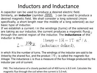
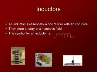
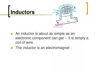
6.4 Inductors • An inductor is made of a coil of conducting wire
Fig 6.23 • air-core • (b) iron-core • (c) variable iron-core
Flux in Inductors • The relation between the flux in inductor and the current through the inductor is given below. ψ Linear Nonlinear i
Energy Storage Form • An inductor is a passive element designed to store energyin the magnetic field while a capacitor stores energy in the electric field.
I-V Relation of Inductors i • An inductor consists of a coil of conducting wire. + v L -
Physical Meaning • When the current through an inductor is a constant, then the voltage across the inductor is zero, same as a short circuit. • No abrupt change of the current through an inductor is possible except an infinite voltage across the inductor is applied. • The inductor can be used to generate a high voltage, for example, used as an igniting element.
Fig 6.25 • An inductor are like a short circuit to dc. • The current through an inductor cannot change instantaneously.
+ v L -
Energy Stored in an Inductor • The energy stored in an inductor + v L -