Sequencing and Control
Sequencing and Control. Mano and Kime Sections 8-1 – 8-7. Sequencing and Control. Algorithmic State Machines Binary Multiplier Hardwired Control Binary Multiplier – VHDL Microprogrammed Control. Algorithmic State Machine. ASM Block. Timing. Sequencing and Control.

Sequencing and Control
E N D
Presentation Transcript
Sequencing and Control Mano and Kime Sections 8-1 – 8-7
Sequencing and Control • Algorithmic State Machines • Binary Multiplier • Hardwired Control • Binary Multiplier – VHDL • Microprogrammed Control
ASM Block Timing
Sequencing and Control • Algorithmic State Machines • Binary Multiplier • Hardwired Control • Binary Multiplier – VHDL • Microprogrammed Control
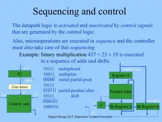
An Algorithmic Binary Multiplier Either adding the multiplier or 0000
Shifting partial product right is the same as shifting the multiplier to the left
If GO Then Initialize the multiplier
If the right-most bit of the multiplier in the Q shift register is 0 then goto state MUL1
Otherwise, if the right-most bit of the multiplier is 1 then add the partial product (A) to the multiplicand (B) and store it in A. Prepare to shift in C.
Shift a 0 into C, shift right C || A || Q into C || A || Q Decrement P C || A || Q denotes a composite register.
If Z = 1 then we have gone through the state machine n -1 times and we are finished
Otherwise, if Z = 0 we continue back to state MUL0.
Register A contains the four most significant bits of the product and Register Q contains the four least significant bits of the product when we are finished. Note that n-bits x n-bits <= 2n bits
Sequencing and Control • Algorithmic State Machines • Binary Multiplier • Hardwired Control • Binary Multiplier – VHDL • Microprogrammed Control
Let’s take a closer look at the control unit
Decoder outputs based off of the present state --The decoder plays role in controlling the next state
00 01 10
ASM chart transformation rules with one flip-flop per state Notice two flip flops for the two states, MUL0 and MUL1
Idle Junction (from Z and G) Idle State Decision Box junction State MUL0 State MUL1 Z Decision Box
Sequencing and Control • Algorithmic State Machines • Binary Multiplier • Hardwired Control • Binary Multiplier – VHDL • Microprogrammed Control
VHDL -- Binary Multiplier with n=4; VHDL Description library ieee; use ieee.std_logic_1164.all; use ieee.std_logic_unsigned.all; entity binary_multiplier is port(CLK, RESET, G, LOADB, LOADQ: in std_logic; MULT_IN: in std_logic_vector(3 downto 0); MULT_OUT: out std_logic_vector(7 downto 0)); end binary_multiplier;
architecture behavior_4 of binary_multiplier is type state_type is (IDLE, MUL0, MUL1); signal state, next_state : state_type; signal A, B, Q: std_logic_vector(3 downto 0); signal P : std_logic_vector(1 downto 0); signal C, Z: std_logic; begin Z <= (P1) NOR P(0); MULT_OUT <= A & Q; state_register: process (CLK, RESET) begin if (RESET = ‘1’) then state <= IDLE; elsif (CLK’event and CLK = ‘1’) then state <= next_state; end if; end process; State Machine
next_state_func: process (G, Z, state) begin case state is when IDLE => if G = ‘1’ then next_state <= MUL0; else next_state <= IDLE; end if; when MUL0 => next_state <= MUL1; when MUL1 => if Z = ‘1’ then next_state <= IDLE; else next_state <= MUL0; end if; end case; end process; Next State
DATAPATH datapath_func: process (CLK) variable CA: std_logic_vector(4 downto 0); begin if (CLK’event and CLK = ‘1’) then if LOADB = ‘1’ then B <= MULT_IN; end if; if LOADQ = ‘1’ then Q <= MULT_IN; end if; case state is when IDLE => if G = ‘1’ then C <= ‘0’; A <= “0000”; P <= “11”; end if; when MUL0 => if Q(0) = ‘1’ then CA := (‘0’ & A) + (‘0’ & B); else CA := C & A; end if; C <= CA(4); A <= CA(3 downto 0); when MUL1 => C <= ‘0’; A <= C & A(3 downto 1); Q <= A(0) & Q(3 downto 1); P <= P - “01”; end case; end if; end process; end behavior_4;
Sequencing and Control • Algorithmic State Machines • Binary Multiplier • Hardwired Control • Binary Multiplier – VHDL • Microprogrammed Control
In general… Microprogrammed Control Unit Organization Addresses lookup table Acts like a control output lookup table
Note 5 states Basic ASM Chart from initial design ASM Chart for microprogrammed Control Unit
What do we store in our lookup ROM? Next state (1 or 5) A Micro-instruction Control Word
Control Signals With this in mind, we need to design the control words...