Accelerator Physics Challenges in 3 rd Generation Synchrotron Light Sources
590 likes | 827 Vues
Accelerator Physics Challenges in 3 rd Generation Synchrotron Light Sources. R. Bartolini John Adams Institute and Diamond Light Source Ltd. Summary. Introduction: synchrotron radiation storage ring synchrotron radiation sources Accelerator Physics challenges:

Accelerator Physics Challenges in 3 rd Generation Synchrotron Light Sources
E N D
Presentation Transcript
Accelerator Physics Challenges in 3rd Generation Synchrotron Light Sources R. Bartolini John Adams Institute and Diamond Light Source Ltd
Summary Introduction: synchrotron radiation storage ring synchrotron radiation sources Accelerator Physics challenges: brightness, flux, stability, time structure Conclusion: future trends 3rd generation vs 4th generation
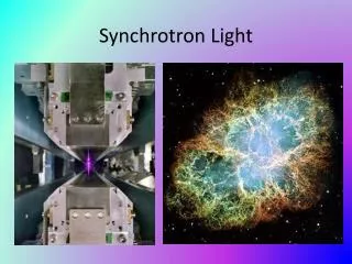
What is synchrotron radiation Electromagnetic radiation is emitted by charged particles when accelerated The electromagnetic radiation emitted when the charged particles accelerated radially (v a) is called synchrotron radiation . It is produced in the synchrotron radiation sources using bending magnets undulators and wigglers
storage ring synchrotron radiation sources (II) Courtesy Z. Zhao
storage ring synchrotron radiation sources (III) Courtesy Z. Zhao
synchrotron radiation sources properties synchrotron light Broad Spectrum which covers from microwaves to hard X-rays: the user can select the wavelength required for experiment High Flux and High Brightness: highly collimated photon beam generated by a small divergence and small size source (partial coherence) High Stability: submicron source stability Polarisation: both linear and circular (with IDs) Pulsed Time Structure: pulsed length down to tens of picoseconds allows the resolution of processes on the same time scale Flux = Photons / ( s BW) Brightness = Photons / ( s mm2 mrad2 BW )
X-ray tube 60W bulb Candle diamond Brightness X-rays from Diamond will be 1012 times brighter than from an X-ray tube, 105 times brighter than the SRS !
Life science examples: DNA and myoglobin Franklin and Gosling used a X-ray tube: Brightness was 108 (ph/sec/mm2/mrad2/0.1BW) Exposure times of 1 day were typical (105 sec) e.g. Diamond provides a brightness of 1020 100 ns exposure would be sufficient Nowadays pump probe experiment in life science are performed using 100 ps pulses from storage ring light sources: e.g. ESRF myoglobin in action Photograph 51 Franklin-Gosling DNA (form B) 1952
312 ns 312 ns Time structure Time resolved science requires operating modes with single bunch or hybrid fills to exploit the short radiation pulses of a single isolated bunch
Accelerator Physics challenges Small Emittance Insertion Devices (low gaps) High Current; Control Impedance; Feedbacks Control Vibrations; Orbit Feedbacks; Top-Up Short Pulses; Short Bunches Brightness, Flux Stability Time structure
NSLS-II Brightness and emittance The electron beam emittance is a parameter of the storage ring that defines the source size and divergence brightness 1 / emittance
Emittance in an electron storage ring The quantum nature of the synchrotron radiation emission is responsible for the finite beam size, emittance and energy spread of the electron beam. Transverse electron oscillations are excited by the emission of a photon and are damped on average when the electron travels through the RF cavities Oscillation damping and excitation counterbalance and an equilibrium emittance is reached
Small emittance lattices The horizontal emittance is determined by the dispersion generated by the main bending magnets. Low emittance and adequate space in straight section to accommodate long Insertion Devices are obtained in the so called DBA and TBA lattices Theoretical Minimum Emittance
Commissioning of small emittance optics (I) During commissioning the Accelerator Physicists have to ensure that storage ring operates successfully in the nominal linear optics. Linear optics studies are based on the analysis of the closed orbit response matrix (LOCO-like approach) The orbit response matrix R is the change in the orbit at the BPMs as a function of changes in the steering magnets strength V V Using the Singular Value Decomposition (SVD) of the Response Matrix R we can invert R and correct the closed orbit distortion H H
Commissioning of small emittance optics (II) The response matrix R is defined by the linear lattice of the machine, (dipoles and quadrupoles), therefore it can be used to calibrate the linear optics of the machine The quadrupole gradients are used in a least square fit to minimize the distance 2
Quadrupole gradient correction LOCO varies the quadurpoles individually to fit the measured RM; Initially the quadrupole variations generated by LOCO could reach 4%; Quads variation reduced with better closed orbit correction, BBA and SVD threshold for LOCO; Within each family quads variations are less than 2 % with respect to the mean for each quad family. (Up to 5 % with respect to the nominal calibration)
Implementation of small emittance optics The optic functions measured at the BPMs location (circles) agree very well with the measured one (crosses) Residual beta-beating can be reduced to 1% or less
Emittance measurements with two pinhole camera Measured emittance very close to the theoretical values confirms the optics Emittance 2.78 (2.75) nm Energy spread 1.1e-3 (1.0e-3) Emittance coupling 0.5%
Small emittance and nonlinear beam dynamics Small emittance Strong quadrupoles Large (natural) chromaticity strong sextupoles (sextupoles guarantee the focussing of off-energy particles) Courtesy A. Streun strong sextupoles reduce the dynamic aperture and the Touschek lifetime additional sextupoles are required to correct nonlinear aberrations [Consider the effect of realistic errors (and define magnetic error tolerances)]
Chromatic (energy dependent) effect Optics functions vary with relative energy offset The betatron tunes crosses a wide range of resonances with relative energy offset
Nonlinear beam dynamics optimisation (I) • It is a complex process where the Accelerator Physicist is guided by • (semi-)analytical formulae for the computation of nonlinear maps, detuning with amplitude and off-momentum, resonance driving terms • numerical tracking: direct calculation of non linear tuneshifts with amplitude and off-momentum, 6D dynamics aperture and the frequency analysis of the betatron oscillations • Many iterations are required to achieve a good solution that guarantees a good dynamic aperture for injection and a good Touschek lifetime
Nonlinear beam dynamics optimisation (II) The Dynamic Aperture problem Frequency Map Analysis allows the identification of dangerous non linear resonances during design and operation Vacuum chamber ALS measured ALS model Strongly excited resonances can destroy the Dynamic Aperture
Touschek lifetime Electrons performing betatron oscillations may scatter and be lost outside the momentum aperture available from RF voltage and the 6D dynamic aperture Synchrotron radiation light sources require a large off-momentum aperture The full 6D dynamic aperture has to be optimised
How to achieve and even smaller emittance Reduce the emission of radiation in bending magnets with either lower energy or weaker magnetic field → larger circumference (NSLS-II, Petra-III, PEP, Tristan). The radiated energy is proportional to E2B2 Damping wiggler in the storage ring (NSLS-II, PETRA-III): beam dynamics still manageable; sub-nm emittance looks feasible ! Tailor the magnetic field in the dipole – azimuthal dependence - in order to reduce the integral of the dispersion invariant in the dipole (studies ongoing at ESRF, SLS, Soleil): Dynamic Aperture correction quite complicated;
Closed Orbit correction and orbit stability The beam orbit is corrected to the BPMs zeros by means of a set of dipole corrector magnets: the BPMs can achieve submicron precision and the orbit rms is corrected to below 1 m:
Closed orbit disturbances • ground settling • tidal motion • day/night (thermal variations) • re-injection • thermal drifts of the electronics • insertion device gap movements • ground vibrations • air conditioning units • refrigerators, compressor (cooling systems) • power supplies • cooling water flow • high current instabilities Courtesy C. Bocchetta
Stability requirements in 3rd generation light sources Beam stability should be better than 10% of the beam size and divergence but IR beamlines will have tighter requirements Courtesy L. Farvacque For Diamond nominal optics (at the centre of the short straight sections)
Beam vibrations induced by ground and girder vibrations Integrated H Girder 1 PSD 0.090 um Integrated H Girder 2 PSD 0.088 um Integrated H Girder 3 PSD 0.072 um Integrated H Ground PSD 0.018 um Integrated H Beam PSD 2.41 um
Beam stability at the source points (1-100Hz bandwidth) We are within 10% of the beam size and divergence without FOFB
Performance of Diamond FOFB Significant improvement up to 100 Hz; higher frequencies performance limited mainly by the correctors power supply bandwidth
Long term drifts (30 minutes) SOFB OFF 3 m maximum drift over 30 minutes H rms < 0.7 m V rms < 0.4 m
Long term drifts (30 minutes) SOFB ON SOFB running at 0.2 Hz H rms < 0.5 m V rms < 0.3 m
Improving stability: Top-Up operation (I) • Top-Up operation consists in the continuous (very frequent) injection to keep the stored current constant • Top-Up improves stability • constant photon flux • constant thermal load on components • provides more flexibility • Lifetime less important • Smaller ID gaps • Lower coupling • Already in operation at APS and SLS
Improving stability: Top-Up operation (II) • Total current stable at 128.4mA to 0.1% • Hybrid bunch stable at 0.43mA to 3.2% Pk-pk ~ 0.2mA σ ~ 0.06mA
Safety case for Top-Up operation Beam-line safe for top-up if: 1. Electrons travelling forwards from straight section cannot pass down beam-line 2. Electrons travelling backwards from beam-line cannot pass through to straight section 3. Electrons travelling in either direction do not have same trajectory at any intermediate point Machine Interlocks have to be defined to prevent a top-up accident under faulty conditions: BTS energy ILK and stored beam ILK are adequate for Diamond
AP challenges: Time structure Diamond present layout: Injector and timing allow a very flexible fill pattern control (single bunch – camshaft, etc) but bunch length limited to 10 ps Rep rate higher than 533 kHz 312 ns 312 ns The bunch length and energy spread, increase with current due to the "microwave instability":
Generation of short radiation pulses in a storage ring There are three main approaches to generate short radiation pulses in storage rings e– bunch 1) shorten the e- bunch 2) chirp the e-bunch + slit or optical compression 3) local energy-density modulation Low – alpha Higher Harmonic Cavities RF voltage modulation Crab Cavities Synchro-betatron kicks Femto – slicing
Bunch length (low current) The equilibrium bunch length is due to the quantum nature of the emission of synchrotron radiation and is the result of the competition between quantum excitation and radiation damping. If high current effects are negligible the bunch length is z = 2.8 mm (9.4 ps) = 1.710–4; V = 3.3 MV; = 9.6 10–4 z depends on the magnetic lattice (quadrupole magnets) via We can modify the electron optics to reduce z 0.3 mm (1 ps) (low_alpha_optics) 10–6
Low alpha optics When the bunch is too short Coherent Synchrotron Radiation generates further instabilities Microbunch instability (Stupakov-Heifets) for Diamond the Microbunching threshold is about 10 A per bunch at 1 ps rms length Single bunch: 10 A; 1 ps; rep. rate 530 kHz Full fill: 10 A * 936 bunches; 1 ps; rep. rate 500 MHz Bessy-II data Courtesy P. Kuske Bessy-II, ALS and SPEAR3 have successfully demonstrated low-alpha operation with few ps bunches for Coherent THz radiation
Crab Cavities for optical pulse shortening Courtesy M. Borland (APS)
A possible implementation of crab cavities at Diamond Crab cavities are located at 1.1 m from the centre of the long straight 4 in V 420 rad V kick Looks feasible to get sub-ps x-ray pulses with very good transmission (80%) Emittance degradation is modest Impedance issues have still to be addressed (machine impedance, LOM and HOM in crab cavity) This scheme is yet unproven
Femto-second slicing fs pulse lW “dark” pulse electron bunch femtosecond laser pulse femtosecond electron bunch fs pulse wiggler electron-laser interaction in the modulator (a) spatial or angular separation in a dispersive section (b) fs radiation pulses from a radiator (c) A.A. Zholents and M.S. Zolotorev, Phys. Rev. Lett. 76 (1996) 912. BESSY-II, ALS and SLS have successfully demonstrated the generation of X-ray pulses with few 100 fs pulse length
Energy modulation generated by a short laser pulse Natural energy spread 0.1%
Separation of the radiation from the two modulated bunchlets max 1.5 % energy modulation Pulse stretching at radiator 35 fs separation x = 1.8 mm (w.r.t. 200 um beam size rms) separation x’ = 0.6 mrad (w.r.t. 0.3 mrad opening angle of radiation) Radiation pulses of 35 fs can be generated; modulator radiator
Crab C. Comparison of options for short radiation pulses
Negative Charged Beam AP challenges: high current operation The beam and its electromagnetic field travel inside the vacuum chamber while the image charge travels on the chamber itself. Any variation on the chamber profile, on the chamber material, breaks this configuration. The beam loses a (usually small) part of it is energy that feeds the electromagnetic fields that remain after the passage of the beam. Such fields are referred as wake fields Wake fields generated by beam particles, mainly affect trailing particles in previous bunches (long range wakes) or in the tail of the same bunch (short range wakes)
AP challenges: High current Collective effect are usually categorised as Multi-bunch and Single-bunch; Transverse and Longitudinal; Main causes in synchrotron light sources are Resistive Wall impedance (narrow gap chambers, SS vacuum chambers) Ion related instabilities (Ion Trapping; Fast Ion Instability) Poor design of vacuum chamber elements (tapers, bellows, BPMs, …) RF cavities High Order Modes (HOMs) Main cures are Operation with high positive chromaticity Bunch lengthening (low voltage RF voltage, Harmonic cavities) Feedback systems (TMBF, LMBF) better design of vacuum chamber elements (SCRF, HOM damping, …)