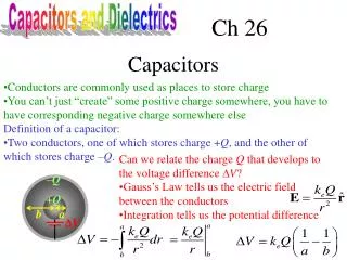
Capacitors with Dielectrics
Capacitors with Dielectrics. AP Physics C Montwood High School R. Casao. Dielectric. A dielectric is a nonconducting material inserted between the plates of a capacitor. A dielectric increases the ability of a capacitor to store energy.

Capacitors with Dielectrics
E N D
Presentation Transcript
Capacitors with Dielectrics AP Physics C Montwood High School R. Casao
Dielectric • A dielectric is a nonconducting material inserted between the plates of a capacitor. • A dielectric increases the ability of a capacitor to store energy. • If the dielectric completely fills the space between the plates, the capacitance increases by a factor k, called the dielectric constant.
Dielectric When a dielectric is inserted between the plates of a charged capacitor that is not connected to a battery (a source of additional charge), but the voltage is reduced by a factor k.
Dielectric • Since the charge Q on the capacitor does not change, then the capacitance must change with the changing voltage so that the charge remains constant. • The capacitance increases by a factor k when the dielectric completely fills the space between the plates. • The dielectric constant is a measure of the degree of dipole alignment in the material.
From the equation for capacitance the capacitance can be increased by decreasing the distance d between the plates. The value of d is limited by the electrical discharge that could occur through the dielectric medium separating the plates. For any separation d, the maximum voltage that can be applied across the capacitor plates without causing a discharge depends on the dielectric strength of the dielectric.
In other words, the maximum electric field the dielectric material can withstand without allowing a transfer of charge between the plates is the dielectric strength. If the electric field strength in the dielectric exceeds the dielectric strength, the insulating properties will break down and the dielectric material begins to conduct. This is called dielectric breakdown.
“Polarization” of a dielectric in an electric field E gives rise to thin layers of bound charges on the dielectric’s surfaces, creating surface charge densities +si and –si.
An Atomic Description of Dielectrics • Polar molecules are randomly oriented in the absence of an external electric field. • When an external field is applied (to the right as shown), the molecules partially align with the field; the dielectric is now polarized.
(a) When a dielectric is polarized, the dipole moments of the molecules in the dielectric are partially aligned with the external field Eo. (b) This polarization causes an induced charge on the opposite side. This separation of charge results in a reduction in the net electric field within the dielectric. The net effect on the dielectric is the formation of an induced positive surface charge density sind on the right face and an equal negative surface charge density –sind on the left face.
The induced surface charge give rise to an induced electric field Eind in the direction opposite the external field Eo.
What is the Magnitude of the Induced Charge Density? For parallel plate capacitor, External field Eo = s/eo Induced Field Eind = sind/eo and E = Eo/k = s/k·eo Substitute into E = Eo - Eind gives Note that the induced charge density on the dielectric is less than the charge density on the plates.
The net electric field in the dielectric is given by: E = Eo - Einduced • The dielectric provides these advantages: • Increases the capacitance of the capacitor. • Increases the maximum operating voltage of a capacitor. • May provide mechanical support between the conducting plates.
Effect of the Dielectric Constant Potential difference with a dielectric is less than the potential difference across free space Results in a higher capacitance. Allows more charge to be stored before breakdown voltage.
Effect of the Dielectric Constant Parallel Plate Capacitor Material permittivity measures degree to which the material permits induced dipoles to align with an external field. Example modifications using permittivity
The energy of the capacitor is lowered when a dielectric is inserted between the plates. Work is done on the dielectric. A force must act on the dielectric which pulls it into the capacitor. The nonuniform electric field near the edges of a parallel plate capacitor exerts this force. The horizontal component of the electric field acts on the induced charges on the surface of the dielectric, producing a horizontal force directed into the capacitor.
Place a dielectric material between capacitor plates: • A charge of -13 is on the right negative plate of the capacitor. • A charge of +7 is on the right positive portion of the dielectric. • The battery sees -13 + 7 = -6 (less total charge on the negative capacitor plate). • To compensate for the absence of charge, the battery sends more charge to the negative capacitor plate to restore the -13 charge. • This is how a dielectric allows for more charge to be stored on the capacitor plates.
Effect of a Metallic Slab Between the Plates A parallel-plate capacitor has a plate separation d and plate area A. An uncharged metallic slab of thickness a is inserted midway between the plates.
Charge on one plate must induce a charge of equal magnitude but opposite sign on the near side of the metallic slab. Net charge on the slab is zero, electric field inside the slab is zero. Capacitor = two capacitor in series, each having a plate separation of (d-a)/2 as shown.
Effect of a Metallic Slab between the plates What are the differences in the result as compared to the previous example if we insert the metallic slab as shown?
A Partially Filled Capacitor A parallel-plate capacitor with a plate separation d has a capacitance Co in the absence of a dielectric. What is the capacitance when a slab of dielectric material of dielectric constant k and thickness d/3 is inserted between the plates as shown.
A Partially Filled Capacitor Two capacitors in series
Two Dielectric Slabs • Consider a parallel-plate capacitor that has the space between the plates filled with two dielectric slabs, one with constant k1 and one with constant k2. • The thickness of each slab is the same as the plate separation d and each slab fills half the volume between the plates. • The two different dielectric slabs represent two capacitors in parallel with a plate area A/2.
Charge Storage Warning • Capacitors can store a charge for a long time after the power to them has been turned off. This charge can be dangerous. • A large electrolytic capacitor charged to only 5 V or 10 V can melt the tip of a screwdriver placed across its terminal. • High voltage capacitors like those in TV’s and photoflash units can store a lethal charge. • Technicians ground themselves to avoid electric shock.