Capacitors
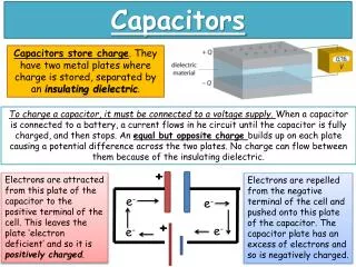
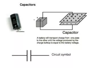
Capacitors. Energy Storage Devices. Capacitors. Composed of two conductive plates separated by an insulator (or dielectric). Commonly illustrated as two parallel metal plates separated by a distance, d. C = e A/d w here e = e r e o e r is the relative dielectric constant


Capacitors
E N D
Presentation Transcript
Capacitors Energy Storage Devices
Capacitors • Composed of two conductive plates separated by an insulator (or dielectric). • Commonly illustrated as two parallel metal plates separated by a distance, d. C = e A/d where e = ereo er is the relative dielectric constant eo is the vacuum permittivity
Effect of Dimensions • Capacitance increases with • increasing surface area of the plates, • decreasing spacing between plates, and • increasing the relative dielectric constant of the insulator between the two plates.
Types of Capacitors • Fixed Capacitors • Nonpolarized • May be connected into circuit with either terminal of capacitor connected to the high voltage side of the circuit. • Insulator: Paper, Mica, Ceramic, Polymer • Electrolytic • The negative terminal must always be at a lower voltage than the positive terminal • Plates or Electrodes: Aluminum, Tantalum
Nonpolarized • Difficult to make nonpolarized capacitors that store a large amount of charge or operate at high voltages. • Tolerance on capacitance values is very large • +50%/-25% is not unusual PSpice Symbol http://www.marvac.com/fun/ceramic_capacitor_codes.aspx
Electrolytic Pspice Symbols Fabrication http://www.digitivity.com/articles/2008/11/choosing-the-right-capacitor.html
Variable Capacitors • Cross-sectional area is changed as one set of plates are rotated with respect to the other. PSpice Symbol http://www.tpub.com/neets/book2/3f.htm
MEMS Capacitor • MEMS (Microelectromechanicalsystem) • Can be a variable capacitor by changing the distance between electrodes. • Use in sensing applications as well as in RF electronics. http://www.silvaco.com/tech_lib_TCAD/simulationstandard/2005/aug/a3/a3.html
Electric Double Layer Capacitor • Also known as a supercapacitoror ultracapacitor • Used in high voltage/high current applications. • Energy storage for alternate energy systems. http://en.wikipedia.org/wiki/File:Supercapacitor_diagram.svg
Electrical Properties of a Capacitor • Acts like an open circuit at steady state when connected to a d.c. voltage or current source. • Voltage on a capacitor must be continuous • There are no abrupt changes to the voltage • An ideal capacitor does not dissipate energy, it takes power when storing energy and returns it when discharging.
Properties of a Real Capacitor • A real capacitor does dissipate energy due leakage of charge through its insulator. • This is modeled by putting a resistor in parallel with an ideal capacitor.
Energy Storage • Charge is stored on the plates of the capacitor. Equation: Q = CV Units: Coulomb = Farad.Voltage C = F V
Adding Charge to Capacitor • The ability to add charge to a capacitor depends on: • the amount of charge already on the plates of the capacitor and • the force (voltage) driving the charge towards the plates (i.e., current)
Charging a Capacitor • At first, it is easy to store charge in the capacitor. • As more charge is stored on the plates of the capacitor, it becomes increasingly difficult to place additional charge on the plates. • Coulombic repulsion from the charge already on the plates creates an opposing force to limit the addition of more charge on the plates. • Voltage across a capacitor increases rapidly as charge is moved onto the plates when the initial amount of charge on the capacitor is small. • Voltage across the capacitor increases more slowly as it becomes difficult to add extra charge to the plates.
Discharging a Capacitor • At first, it is easy to remove charge in the capacitor. • Coulombic repulsion from the charge already on the plates creates a force that pushes some of the charge out of the capacitor once the force (voltage) that placed the charge in the capacitor is removed (or decreased). • As more charge is removed from the plates of the capacitor, it becomes increasingly difficult to get rid of the small amount of charge remaining on the plates. • Coulombic repulsion decreases as the charge spreads out on the plates. As the amount of charge decreases, the force needed to drive the charge off of the plates decreases. • Voltage across a capacitor decreases rapidly as charge is removed from the plates when the initial amount of charge on the capacitor is small. • Voltage across the capacitor decreases more slowly as it becomes difficult to force the remaining charge out of the capacitor.
Capacitor Voltage vs. Time d.c. voltage, Vc, is applied at t = 0s d.c. voltage, Vc, is removed at t = 0s
Time constant, t • The rate at which charge can be added to or removed from the plates of a capacitor as a function of time can be fit to an exponential function. Charging Discharging
Transition to steady state • We approximate that the exponential function reaches its final value when the charging or discharging time is equal to 5t.
Equivalent Capacitance • Capacitors in parallel
Equivalent Capacitance • Capacitors in series
General Equations for Ceq Parallel Combination Series Combination • If P capacitors are in parallel, then • If S capacitors are in series, then:
Summary • Capacitors are energy storage devices. • An ideal capacitor act like an open circuits when a DC voltage or current has been applied for at least 5 t. • The voltage across a capacitor must be a continuous function; the current flowing across a capacitor can be discontinuous. • The equation for equivalent capacitance for capacitors in parallel capacitors in series