Capacitors
Review of electric fields, potential, energy, and capacitance in parallel plate capacitors, including practical examples and calculations. Learn about dielectrics' impact on capacitance and preflight questions on capacitor behavior.


Capacitors
E N D
Presentation Transcript
Physics 102:Lecture 04 Capacitors
Recall from last lecture…..Electric Fields, Electric Potential
q A B Comparison:Electric Potential Energy vs. Electric Potential DVAB: the difference in electric potential between points B and A DUAB : the change in electric potential energy of a charge q when moved from A to B DUAB = q DVAB
Electric Potential: Summary • E field lines point from higher to lower potential • For positive charges, going from higher to lower potential is “downhill” • For negative charges, going from lower to higher potential is “downhill” • For a battery, the + terminal is at a higher potential than the – terminal Positive charges tend to go “downhill”, from + to - Negative charges go in the opposite direction, from - to + DUAB = q DVAB
Important Special CaseUniform Electric Field - - - - - + + + + + • Two large parallel conducting plates of area A • +Q on one plate • - Q on other plate • Then E is • uniform between the two plates: E=4kQ/A • zero everywhere else • This result is independent of plate separation • This is call a parallel plate capacitor
A B Parallel Plate Capacitor:Potential Difference Charge Q on plates Charge 2Q on plates V =VA – VB = +E0 d V =VA – VB = +2E0 d E=2 E0 E=E0 - - - - - + + + + + - - - - - + + + + + - - - - - + + + + + A B d d Potential difference is proportional to charge: Double Q Double V • E0=4kQ/A 10
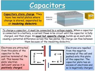
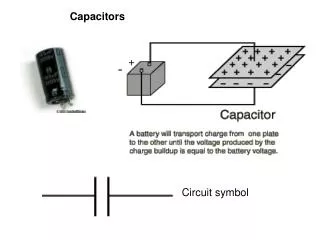
- - - - - + + + + + E d Capacitance: The ability to store separated charge CQ/V • Any pair conductors separated by a small distance. (e.g. two metal plates) • Capacitor stores separated charge • Positive Q on one conductor, negative Q on other • Net charge is zero Q=CV • Stores Energy U =(½) Q V Units: 1 C/Volt = 1 Farad (F) 12
Why Separate Charge? • Camera Flash • Defibrillator—see ex. 17.12 in text • AC -> DC • Tuners • Radio • Cell phones
Example Capacitance Practice How much charge is on a 0.9 F capacitor which has a potential difference of 200 Volts? How much energy is stored in this capacitor? 14
Example Capacitance Practice How much charge is on a 0.9 F capacitor which has a potential difference of 200 Volts? Q = CV = (0.9)(200) = 180 Coulombs How much energy is stored in this capacitor? U = ½ Q V = ½ (180) (200) = 18,000 Joules! 14
Capacitance of Parallel Plate Capacitor V V = Ed E=4kQ/A (Between two large plates) So: V = 4kQd/A Recall: CQ/V So: C = A/(4kd) Define: e0=1/(4pk)=8.85x10-12 C2/Nm2 + E - A A d C =e0A/d Parallel plate capacitor 16
Parallel Plate CapacitorC = e0A/d Calculate the capacitance of a parallel plate capacitor made from two large square metal sheets 1.3 m on a side, separated by 0.1 m. Example A A d 18
Parallel Plate CapacitorC = e0A/d Calculate the capacitance of a parallel plate capacitor made from two large square metal sheets 1.3 m on a side, separated by 0.1 m. Example A A d 18
Dielectric constant (k > 1) Capacitance without dielectric Capacitance with dielectric Dielectric • Placing a dielectric between the plates increases the capacitance. C = k C0 19
+ + + + - - - - -q +q d pull pull ACT: Parallel Plates A parallel plate capacitor given a charge q. The plates are then pulled a small distance further apart. What happens to the charge q on each plate of the capacitor? 1) Increases 2) Constant 3) Decreases Remember charge is real/physical. There is no place for the charges to go. 22
+ + + + - - - - -q +q d pull pull Preflight 4.1 A parallel plate capacitor given a charge q. The plates are then pulled a smalldistance further apart. Which of the following apply to the situation after the plates have been moved? 66% 59% 52% 35% 1)The capacitance increases True False 2)The electric field increases True False 3)The voltage between the plates increases True False 4)The energy stored in the capacitor increases True False C = e0A/d C decreases! E= Q/(e0A) Constant V= Ed :24
ACT/Preflight 4.1 + + + + - - - - -q +q d pull pull A parallel plate capacitor given a charge q. The plates are then pulled a small distance further apart. Which of the following apply to the situation after the plates have been moved? The energy stored in the capacitor A) increases B) constant C) decreases U= ½ QV Q constant, V increased Plates are attracted to each other, you must pull them apart, so the potential energy of the plates increases. :25
ACT/Preflight 4.2 Two identical parallel plate capacitors are shown in end-view in A) of the figure. Each has a capacitance of C. B ) A ) If the two are joined as in (B) of the figure, forming a single capacitor, what is the final capacitance? “More area, means more capacitance .” 63% 7% 30% 1) 2C 2) C 3) C/2 “because C=EA/d. none of these variables are changing so C must be the same when the 2 are joined to form a single capacitor” “2 capacitors become 1 which means that the total capacitance got halved ” 26
Vwire 1= 0 V Vwire 2= 5 V Vwire 3= 12 V Vwire 4= 15 V Voltage in Circuits • Elements are connected by wires. • Any connected region of wire has the same potential. • The potential difference across an element is the element’s “voltage.” Example C1 C2 C3 VC1= 5-0 V= 5 V VC2= 12-5 V= 7 V VC3= 15-12 V= 3 V 28
15 V Ceq 10 V Capacitors in Parallel • Add Areas: Ceq = C1+C2 remember C=0A/d • Share Charge: Qeq = Q1+Q2 • Both ends connected together by wire • Same voltage: V1 = V2 = Veq 15 V 15 V C1 C2 10 V 10 V 30
Parallel Practice Example A 4 mF capacitor and 6 mF capacitor are connected in parallel and charged to 5 volts. Calculate Ceq, and the charge on each capacitor. = 4 mF+6 mF = 10 mF Ceq = C4+C6 Q4 = C4 V4 = (4 mF)(5 V) = 20 mC = (6 mF)(5 V) = 30 mC Q6 = C6 V6 = (10 mF)(5 V) = 50 mC Qeq = Ceq Veq = Q4+Q6 V = 5 V 5 V 5 V 5 V C4 C6 Ceq 0 V 0 V 0 V :34
+Q -Q + + - - Ceq +Q -Q Capacitors in Series • Add d: • Connected end-to-end with NO other exits • Same Charge: Q1 = Q2 = Qeq • Share Voltage:V1+V2=Veq + + + +Q + + C1 + + - + + + + C2 -Q - + - + + 36 +
+Q 5 V +Q -Q + +Q -Q - 0 V -Q Series Practice Example A 4 mF capacitor and 6 mF capacitor are connected in series and charged to 5 volts. Calculate Ceq, and the charge on the 4 mF capacitor. Q = CV 5 V + C4 - Ceq + C6 - 0 V :38
C1 C1 C2 C2 Comparison:Series vs. Parallel Series • Can follow a wire from one element to the other with no branches in between. Parallel • Can find a loop of wire containing both elements but no others (may have branches).
Electromotive Force + • Battery • Maintains potential difference V • Not constant power • Not constant current • Does NOT produce or supply charges, just “pushes” them. - 40
C 2 +q2 -q2 + V2 E +q1 +q3 C C V1 V3 - 1 3 -q1 -q3 Preflight 4.4 A circuit consists of three initially uncharged capacitors C1, C2, and C3, which are then connected to a battery of emf E. The capacitors obtain charges q1, q2,q3, and have voltages across their plates V1, V2, and V3.Which of these are true? • q1 = q2 • q2 = q3 • V2 = V3 • E = V1 • V1 < V2 • Ceq > C1 43
Preflight 4.4 C 2 +q2 -q2 + V2 E +q1 +q3 C C V1 V3 - 1 3 -q1 -q3 A circuit consists of three initially uncharged capacitors C1, C2, and C3, which are then connected to a battery of emf E. The capacitors obtain charges q1, q2,q3, and have voltages across their plates V1, V2, and V3. 1) q1 = q2 Not necessarily C1 and C2 are NOT in series. 2) q2 = q3 Yes! C2 and C3 are in series. 45
Preflight 4.4 10V 7V?? C 2 0V +q2 -q2 + V2 E +q1 +q3 C C V1 V3 - 1 3 -q1 -q3 A circuit consists of three initially uncharged capacitors C1, C2, and C3, which are then connected to a battery of emf E. The capacitors obtain charges q1, q2,q3, and have voltages across their plates V1, V2, and V3. 3) V2 = V3 Not necessarily, only if C1 = C2 4) E = V1 Yes! Both ends are connected by wires 48
Preflight 4.4 10V 7V?? C 2 0V +q2 -q2 + V2 E +q1 +q3 C C V1 V3 - 1 3 -q1 -q3 A circuit consists of three initially uncharged capacitors C1, C2, and C3, which are then connected to a battery of emf E. The capacitors obtain charges q1, q2,q3, and have voltages across their plates V1, V2, and V3. 5) V1 < V2 Nope, V1 > V2. (E.g. V1 = 10-0, V2 =10-7 6) Ceq > C1 Yes! C1 is in parallel with C23 48
Recap of Today’s Lecture • Capacitance C = Q/V • Parallel Plate: C = 0A/d • Capacitors in parallel: Ceq = C1+C2 • Capacitors in series: Ceq = 1/(1/C1+1/C2) • Batteries provide fixed potential difference