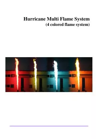
Hurricane Multi Flame System: Create Spectacular Colored Flames
The Hurricane Multi Flame System delivers stunning colored flames, reaching up to 7 meters high. Equipped with a burner head, fluid and gas tanks, and operated via a standard DMX controller, this system allows users to generate a single colored flame from four options (Red, Green, Blue, Gold/Orange). Safety features include flame safeguard technology and built-in pressure sensors. Ideal for events, performances, and special effects, it is designed for safety and ease of use, featuring optional accessories such as a handy DMX controller and pressure regulator for versatile operation.

Hurricane Multi Flame System: Create Spectacular Colored Flames
E N D
Presentation Transcript
Hurricane Multi Flame System (4 colored flame system)
Set of Equipment Supplied • Burner Head :1 • Fluid Tank : 1 • Signal Cable : 1 • Power Cable : 1 • Fluid Hose : 4(35~40cm/hose) • Gas Hose : 1 • Operation Manual: 1 • Optional Accessories • Handy DMX Controller • Pressure Regulator • Longer Fluid Hose than standard length • Road Case
Contents 1. INTRODUCTION 1.1 Introduction 1.2 Specification • 1.3. Operator shall prepare following accessories for using Hurricane System. 2. DESCRIPTION OF THE PARTS 2.1. Burner Head 2.2. Fluid Tank 2.3. Fluid Hose 2.4. Gas Hose 2.5. Pressure Regulator and Gas Distributor 2.6. Propellant Source 2.7. Cables 2.8. Fuel Sources 2.9. Handy DMX Controller 3. GENERAL OVERVIEW 3.1. General Operation of Flame System 3.2. Operators must 4. SAFETY OVERVIEW 4.1. Equipment provided 4.2. Basic Setup 4.3. Safety 4.4. Additional Safety Information 5. CLEANING & MAINTENANCE 5.1. Cleaning & Maintenance 5.2. Trouble Shooting 6. DMX ADDRESSING 6.1. DMX Address No. 6.2. How to set address No. 6.3. Connection of Multiple Burner Heads
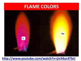
1. INTRODUCTION 1. 1. Introduction Hurricane Multi Flame Systemcan fire your desired single colored flame among four colored flames on demand. Using our Colorfirefly SFX fluid for main flame and Nitrogen Gas as propellant, the system gives you the ability to shoot a specific colored flame up to seven meter(24 ft) high on average. Hurricane Multi Flame System is the system that SFX fluid is propelled into the air by 2.0MPa (290psi) of Nitrogen Gas, being lit by pilot flame and produced into a beautiful single colored flame pillar at the height of seven meter (24ft) on average. Onboard flame safeguard technology and pressure safety sensor system helps insure a safe and reliable colored flame effect. The system can be controlled by Standard DMX Controller. 1. 2. Specification • Power : 110VAC or 220VAC, 1 amp, 50/60Hz. • Burner Head : 24cm(W) x 34cm(H) x 35cm(L)/15KG • Fluid Tank : 61cm(W) x 71cm(H) x 43cm(L)/35KG • Road cased system : 58cm(W) x 90cm(H) x 70cm(L)/85KG • Flame Height : 7 meter(24 feet) on average. • Tank Size : 11 Liter (2.9 gallon)/tank (7 liter – 1.85gallon- for Fluid and • 4 Liter – 1.05 gallon- for Nitrogen Gas). Total 4 tanks installed. • Shooting Duration : 9 sec./liter (Total 252 Sec./28 liter. - 7 liter x 4 tanks) • Uses Nitrogen Gas as a propellant. • Working Pressure : 2.0 – 2.5MPa(290 - 355psi) • Control : Standard DMX 512 Controller. • Pilot fuel sources : Butane Fuel Canister(220~250gram - 8oz) • Main flame source : SFX fluid (Red, Green, Blue, Gold or Orange) 1. 3. Operator shall prepare following accessories for using Hurricane System. • Standard DMX 512 Controller (3 pin DMX). • Nitrogen Gas Tank • Pressure Regulator : It is integral to the hose system and Nitrogen Gas Tank system. • The regulator, which can regulate the pressure range of 0 ~ 5.0 or 6.0MPa is recommended. The working pressure is 2.0MPa(290psi). So, the regulator should regulate at least 2.0MPa. Also, it is recommended to install a gas vent valve on the one end of regulator for removing the remaining gas inside the gas hose after show. • Gas Distributor : In case that you connect multiple units to one gas tank, you need gas distributor to be connected to hose from one nitrogen gas tank. Our gas distributor can connect 4 units of Hurricane System to a gas tank. • SFX Fluid
2. DESCRIPTION OF THE PARTS 2. 1. Burner Head • The burner head houses the pilot valve, the main flame valves, the pilot assembly, and the • rectification flame sensor. During the arming sequence, the flame safe guard creates a high • voltage spark plug on the pilot assembly. The pilot valve is energized and a solid pilot flame • should be established. The rectification sensor will detect the pilot flame and report back to • its control that a solid pilot has been established. Upon detection of a solid pilot flame, • the main flame firing circuit is armed. Only then, main colored flame can be issued. 2. 1. 1. Top View 4 main flame nozzles, one pilot nozzle, igniter and rod type flame sensor are installed inside the burner head. Each main flame nozzle is assigned a specific flame color (Red, Green, Blue and Gold). E-Stop : The E-Stop button provides you a mean • to stop the entire flame system in the event of an • emergency. Pushing this button will disconnect • the electrical power to the system. Power is disconnected • to the flame circuits including ignition, pilot and main flame • valves. To disengage E-Stop, turn it in the arrow direction. • This will return the system to a ready state. • Note : Hazardous live voltage is still accessible inside • the system, while E-Stop is pressed. • Pilot Fuel and DMX address Setting Switch • Open the door and insert butane canister or • Set DMX addressing. 2. 1. 2. Side View On the Connection panel of Burner Head, power switch, Plug socket, DMX signal cable input and output ports, and fuse are installed. Nitrogen Gas input Connect Nitrogen Gas Hose from Nitrogen Gas Tank to this Input.
2. DESCRIPTION OF THE PARTS 2. 2. Fluid Tank Fluid Tank : 4 Fluid Tanks are connected each other. Each fluid tank can be filled with one of SFX fluids. Its capacity is 11 liter but you can fill only 7 liters of fluid into each tank. The rest 4 liter space is for propelling gas. • Fluid Inlet Valve : For filling fluid into each tank, • open valve and pour fluid into tank. After filling fluid, • you have to close valve tightly without fail. • If valve is not closed tightly, the fluid can be burst out of tank • while the propelling gas is supplied into each tank. • Also, after the show, open this fluid inlet valve bit by bit • and very slowly for removing the gas inside the tank. • Don’t open this valve during show or during charging • Nitrogen Gas. If you open this valve abruptly and rapidly, • the compressed fluid will be burst out from the tank and • it can cause dangerous situation and fire. Pressure Gauge : Indicate the inner pressure of fluid tanks. Before shooting flames, always check if the gauge indicates 2.0 – 2.5MPa. Fluid Valve : Using spanners, connect the fluid hoses to each fluid valve and then burner head tightly and completely. In case that you use only one colored fluid tank, NEVER FORGET to close the valves of the not-used other fluid tanks. This FLUID VALVE is also used for draining the remaining fluid of each tank. Locate the tank on the table, disconnect the fluid hoses from burner head and then, put each disconnected hose into each fluid container. Then, open this fluid valve for draining remaining fluids. Fluid Valve You can disconnect the burner head from fluid tank by making these bolts loosen.
2. DESCRIPTION OF THE PARTS 2. 3. Fluid Hose We supply four Fluid Hoses (Standard length : 30 ~ 40cm) together with this system. Each Fluid Hoses should be assigned to a specific colored flame fluid respectively during its shelf life. Fluid Hoses shelf life is 6 months from the first date of use. After that period, don’t use them and replace to new ones. Especially, our blue colored fluid has the characteristics to make the plastic materials hardened and discolored bit by bit. So, always inspect the fluid hoses before use and if you found any defect, replace it to new one immediately. If you need longer fluid hose than the standard one, we can make it longer according to your request. Periodic inspection of the hoses and replacement of defective unit is mandatory. Care must be taken to protect the hoses from physical, thermal or chemical damage. Safety is the non-negotiable topic. 2. 4. Gas Hose We supply 15 meter (50ft) long gas hose per unit. Integral to the Gas Hose system is the pressure regulator of Nitrogen Gas Tank. When you use multiple systems, you need Gas Distributor, which should be installed between the pressure regulator and the gas hose. • Periodic inspection of the hoses and replacement of defective unit is mandatory. • Care must be taken to protect the hoses from physical, thermal or chemical damage. 2. 5. Pressure Regulator and Gas Distributor • Pressure regulator is mandatory for using Hurricane System. Direct 1st outlet pressure from • Nitrogen Gas Tank is very high (usually 25MPa) and if its high pressure is charged into each • tank and burner head, the system and other components can be destroyed or exploded. • Use the pressure regulator which can regulate the secondary outlet pressure ranged from • 0 ~ 5.0MPa from gas tank. When you use your own pressure regulator, you have to install • a vent valve on the one end of regulator. This vent valve is used to remove the remaining • gas inside the gas hose after the show. • Also, when you connect multiple units to one Nitrogen Gas Tank, you need a gas distributor, • which can be connected to multiple gas hoses from one Nitrogen Gas Tank. • Our Gas distributor can connect 4 gas hoses. • 2. 6. Propellant Source (Nitrogen Gas Tank) • Most of Nitrogen Gas Tank has very high outlet pressure. So, if there is no regulator on • Nitrogen Gas Tank, high-pressured Nitrogen Gas can flow directly into each system and • cause damages of system’s components such as regulator, valves, fluid tanks and other • components. In case of using high pressured Nitrogen Gas Tank, install absolutely the • pressure regulator on Nitrogen Gas Tank without fail. • You can connect 4 units of systems to one Nitrogen Gas Tank (Gas Tank Capacity : 40L). • Gas consumption is 25sec./L on average under standard working pressure(2.0MPa).
Flash Button Fire Button Non-Use Pilot Button 2. DESCRIPTION OF THE PARTS • 2. 7. Cables The supplied signal cable is 3 PIN cable, which is set between burner heads and dmx source. Each system can be linked together, using the supplied signal cable to form a DAISY CHAIN run. Take precautions to prevent these cables from getting damaged. Any damaged cables Must be repaired or replaced immediately. We provide 10 meter long signal cable. One cable per unit. • 2. 8. Fuel Source • The fuel source for this system is a two part system. Butane or propane vapor is used for • The pilot flame and Colorfirefly SFX fluid is used for the main colored flame effect. • SFX fluid consists of 5 colored flame fluids, RED, GREEN, BLUE, GOLD and ORANGE. • The pilot flame is drawn from a 220-250gr(8oz) Butane or Propane fuel canister that is • housed inside the burner head. Keep the pilot canister away from sources of heat. • If you want to see its sample, please visit www.iwatani.com and see Butane Fuel • (Model No. High-Power BU5 or 6). • 2. 9. Handy DMX Controller • Hurricane Multi Flame System accepts standard DMX 512 signal and it can be controlled by • Standard DMX 512 controller. Also, we designed the Handy DMX Controller, which can • Operate this hurricane system. • Handy DMX Controller is powered with 12V and its function is as follows ; • - Pilot Button : To light pilot flame. • - Flash Button : While flash button is pushed, Hurricane can shoot the flame only when you • touch the fire buttons. • - Fire Button : 4 buttons are working. (Button No. 1, 2, 3, and 4). • * Button No. 5 is not used.
3. GENERAL OVERVIEW 3.1 General Operation of Flame System Read this manual completely and understand all of the topics before attempting to operate the color flame effect system. Extreme caution is to be taken at all times when servicing and operating this system. At no time should any person orient themselves in direct line with the output of this system. Special care must be taken to prevent accidental discharge of this system. Lock out and tag out procedures must be adhered to at all times when this system is not in show mode. 3.2 Operators must : • Understand and be familiar with the operating manual and instructions. • Acquire hands-on experience in the operation of the effect system. • Demonstrate competency by experience and training. • Demonstrate conceptual and operational knowledge of the system’s components and their interaction. • Be responsible for storage, setup, operation and strike of the flame effect equipment and the supervision of any assistants. • Be at least 21 years of age. • Never use or handle flame effects while under the influence of any substance that can impair judgment, such as intoxicating beverages, narcotics or controlled substances, prescription or non-prescription drugs. • At no time should any changes be made to the control software, hardware configuration, or wiring without the expressed, written permission of GnG. • Servicing is to be performed only by GnG personnel. Appropriate safety equipment is to be worn at all times when handling or servicing the system. Safety is not negotiable topic. • The design of this system and its operating software is proprietary information. • No mechanical copying or alteration of the system is allowable. • The responsibility for safe operation of this system is in the hands of the operator. • At no times should it be operated in an unsafe manner. • The system must be rendered safe when not in use. Administrative and physical measures must be taken to prevent use of the flame system by unqualified personnel.
4. SAFETY OVERVIEW 4.1 Equipment provided This effect system is intended to provide a colored special effect flames. As with all potentially dangerous special effects, the operator should be in full view of the whole systems at all times during operation. 4.2 Basic Setup • Inspect the entire system to make sure that no damage has occurred in transit or • since its last use. Please confirm that the power switches of Burner Head and Controller are turned off. • Place the master control panel at the operator’s firing position. Master control is • defined as any DMX source. • Place the burner head and fluid tank in its desired location and place Nitrogen Gas Tank in the safe and isolated place. Check that nitrogen gas tank’s valve is closed. • Insert Butane Canister to each burner head. Butane Canister is a fuel for pilot flame. • Then, install Pressure regulator to the nitrogen gas tank, then connect gas distributor to pressure regulator and then connect gas hoses to the gas distributor. Finally, connect the gas hoses to each fluid tank units. • Connect fluid hoses from fluid tank to burner head. Always locate fluid hoses in a safe and isolated place free from flammable or sharp objects. Before you connect or disconnect the fluid hoses, NEVER FORGET to close the fluid valve beforehand. • Open fluid inlet valves of fluid tank and pour your desired color fluid into each tank. Our recommended fluid quantity is 7 liter(1.85 gallon) per tank. Don’t pour over 7 liter per tank. After fluid filling, close the fluid inlet valves of the fluid tanks tightly. • Please open the fluid input valves of burner head and the fluid output valves. • Check for any leaks or damage in the hoses, valves as well as any Butane or • Colorfirefly SFX fluid leaks associated with any other type of damage. • Run and connect the signal cable from the Controller to each burner head. • If multiple burner heads are being used, the signal cable should be connected to • the first burner head , then link the next burner head in line using a new signal cable to create a Daisy Chain and so on. Then, connect power cable to burner head and then, switch on. Before you connect or disconnect signal cable to or from burner head, always keep power off the switch of Controller. Under power-on state of controller, burner head may misfire the flames and it cause critical danger situation. • Open main valve of Nitrogen Gas Tank and then turn the handle of regulator slowly, which is attached to Nitrogen Gas Tank, for setting outlet pressure of 2.0MPa(290psi) • Check and set the pressure of Nitrogen Gas supply for your operating pressure. Pressure should be set at no less than 1.5MPa(213psi) and no greater than 2.5MPa • (355psi). • Check for any leaks or damage again in the hoses, valves as well as any Gas or Colorfirefly SFX Fluid leaks associated with any other type of damage. • Turn on power switches of burner head and controller. Arm the system using pilot button and test fire the main flames.
4. SAFETY OVERVIEW • If the first Burner Head in a chain is assigned address 1, the controls on the master • controller would be as follows : • Burner Head #1 Burner Head # 2 Burner Head #3 Burner Head #4 • CH.1: Red Flame CH.5: Red Flame CH.9 : Red Flame CH.13: Red Flame • CH.2: Green Flame CH.6: Green Flame CH.10: Green Flame CH.14: Green Flame • CH.3: Blue Flame CH.7: Blue Flame CH.11: Blue Flame CH.15: Blue Flame • CH.4: Gold Flame CH.8: Gold Flame CH.12: Gold Flame CH.16: Gold Flame • Etc, Etc, Etc. • Pilot Flame is assigned to CH. 100. • After the show and using the system, you must render it safe before packing it or leaving it unattended. • Power off controller and burner head at first. Then, close the main valve and the handle of the regulator of Nitrogen Gas Tank. • Disconnect power cables and then signal cables. Also, remove butane canister from burner head. • Open the fluid inlet valve bit by bit and slowly for removing pressure from fluid tanks. If you open this fluid inlet valve abruptly and rapidly, the pressured fluids remaining inside the tank can be burst out from fluid tanks and it can cause fire or damage. Please keep in mind that you have to open fluid inlet valve bit by bit and very slowly. • Plug out gas hoses from fluid tanks. • Close fluid input valve of burner head and fluid output valve of fluid tanks and disconnect fluid hoses from burner heads. In this case, fluids remaining inside each fluid hose can be flowed out on the floor. Prepare any container for this flow-out beforehand. • Remove the remaining fluids from the fluid tanks through fluid hoses. • Then, disconnect fluid hoses from fluid tanks. • After drain the remaining fluid completely, pour small quantity of water into the tank • and then drain it again. It is better for you to clean the inside part of the tank with water. Clean burner head and controller with wet naps or paper Towel and cleaning solution. • AVOID SPRAYING CLEANING SOLUTION INSIDE THE BURNER HEAD. • CAUTION : Burner head may be very HOT!!!. Allow it to cool before handling, • packaging or placing in close proximity to flammable materials. • Each fluid hose and fluid tank are marked with fluid color. • It is the best for you to assign each fluid hose and fluid tank to each specific colored flame. Don’t mix or change in using.
4. SAFETY OVERVIEW 4. 3. Safety • Every efforts must be made to insure the following: • There is no Gas or fluid leakage from each flame system and hoses. • That there is a constant supply of Nitrogen Gas, no less than 1.5MPar(213psi) and no greater than 2.5MPa(355psi) for SFX Fluid. • Hoses used should be checked for cracks, holes and other possible damage that may cause fluid or gas leaks. Especially the hoses of blue colored SFX Fluid can be hardened and cracked thanks to some chemical characteristics of Blue SFX Fluid as time goes by. Please replace the hardened hoses to new one at the appropriate time. The Shelf Life of Fluid Hoses is 6 months from the first-used date. • After 6 months are passed, you must replace them to new ones without fail. • * Breaks can be detected by several means. A rich soap-and-water solution can be • sprayed directly on the gas connections; any bubbles or foam creation indicates a leak. Commercially available electronic leak detectors can be used also. • Any leaks must be repaired immediately. • WARNING Fire or explosion hazard can cause property damage, severe injury, • or death. If you smell gas or suspect a leak. Do not introduce a source of ignition • or touch any electrical switch until you are sure that no spilled gas or SFX Fluid • remains present. • In all applications, you should insure that any materials in close proximity to the • system do not reach high temperature from the radiant heat. This is most easily • achieved through the use of a non-contact infrared temperature probe. • These are available from many commercial supply stores. • An approved fire extinguisher must be present at all times when gas is present. • Do not overlap signal cables with power cables. High voltage power of power cable • can cause some noise to signal cable and it causes misfire of the system. • This system is designed to provide short duration of flame effects. • The most frequently used effects are the burst of 1.0-second duration, but no less than 0.5-second duration. Shorter burst times could result in improper itemization of fluid resulting in a misfire. • The effect system is designed for outdoor use. Extra caution should be taken into consideration when using this system indoors. Special care must be taken to prevent the control panel and burner head from getting wet. If these components do get wet, disconnect them from electric power and the gas tank. The control panel should then be opened and allowed to dry before use. • CAUTION : Burner head may be very hot !!! Allow it to cool before handling, • packaging or placing in close proximity to flammable materials. • WARNING Electrocution hazard can cause serious injury or death. • DO NOT touch the spark terminal. The ignition circuit generates over 10,000 volts • and electric shock can result.
4. SAFETY OVERVIEW 4. 4. Additional Safety Information • The electrical rating of the extension cord must be greater than or equal to the electrical rating of this effect system. Use an extension cord suitable for outdoor use when used in an outdoors application. • Do not abuse any electrical cord. Never yank it to disconnect from the receptacle. • Keep all cords away from heat, flammable substances and sharp objects. • The connection between the system and the extension cord must always remain dry and clean at all times. • Disconnect the burner head from the power supply when no in use, while changing Butane fuel canister for pilot flame or Nitrogen Gas tank as a propellant, before servicing, cleaning, etc. • Do not insert foreign objects in this system. • Always check if hoses of Nitrogen Gas and Fluid Hoses have damages or breakages. Also, check if the regulator of Fluid Tank and Nitrogen Gas Tank work in order or not. • Always check signal cables and power cables before using if they are damaged. • To avoid electric shock, DO NOT clean the burner head by spraying water or immersion in water. • Only qualified service personnel may perform all repairs to this effect system. • Read and follow all instructions and warnings affixed to the butane fuel canister and SFX fluid bottles. • All personnel should be carefully supervised when they are in area of the system. • Clothing or other flammable materials should not be hung from the system or placed on or near the system. • Any guard or other protective device removed from servicing the system must be replaced prior to operating. • It is imperative that the system is kept clean at all times. • The system shall be used only in a well-ventilated space and shall not be used in any enclosed area. • The system should be stored indoors when not in use and kept away from children. • Butane Fuel Canister for pilot flame must be removed from the burner head and SFX Fluid should be drained from the fluid tanks completely for storage and transportation after the show. • Keep the area around the system clear and free from combustible materials, gasoline, and any other flammable vapors and liquid.
5. CLEANING & MAINTENANCE 5. 1. Cleaning & Maintenance • Ensure the pilot vents are not clogged by dust. If necessary, remove the dust with strong compressed air gun. Under the cold weather, the pilot fuel may not be gasified very well and so that the pilot flame can’t be solid. In this case, keep Butane Canisters warm a little and use them. • Do not run the system without any fluids, pilot fuel and propellant Gas. • Wipe out spilled fluid immediately. Moisture-also fluid – can destroy the electrical parts of the system. • SFX Fluids can rust the system. After using, wipe out fluids outside of the system with wet naps or paper towel and cleaning solution. Always drain the remains of fluid inside the tank completely and drain again after pouring small quantity of water into the tank. • In case that you cannot drain the remaining fluid immediately after show, keep the valves of Fluid Tank close tightly for preventing air or vapor from being flowed in and out. But don’t forget to drain the remaining fluids by the next day. • Ensure that fluids and pilot fuel were removed from each system. • The vapor of SFX Fluid may damage and harm the printed circuit board and other electronic components so that it can cause troubles to the system. • Clean the fluid hoses with wet naps or paper towel. The, store them in safe place. • Keep out of reach of children or don’t allow unqualified people to touch the system. • Cover the burner head with protective device in order not to be dusted on. • Store the system in clean, dry and cool area away from flammable or heat sources. • Check periodically the hoses, cables and the whole system, if they are damaged. • 5. 2. Trouble Shooting • Pilot Flame is not lighted or flickering and gone. Check the followings ; • - if Pilot Fuel is enough or not. • - if Pilot nozzle or vent is clogged with dusts or not. If clogged, remove dusts by • using strong compressed air gun or change the pilot nozzle. • - if Igniter generates spark or not. If not, it is the trouble of igniter. • - if the flame sensor works or not. If the pilot flame is gone after 5 seconds • after lighting and it repeats to try the re-light of pilot flame with igniter’s spark, • the flame sensor may not sense pilot flame well. Please slightly move the location • of flame sensor to sense the pilot flame well. • - if the pilot valve works correctly or not, please change the pilot valve. • - if the working pressure is appropriate or not. If the working pressure is too high, • the burst of the mixture of Gas and SFX fluid can blow out pilot flame. • If the igniter does not generate the spark, please check the followings : • - After turn the power-switch off the burner, move the location of the igniter • slightly. As time goes by, the location of the igniter can be dislocated. • When changing its location, you must turn off power switch of the burner head. • WARNING Electrocution hazard can cause serious injury or death. • DO NOT touch the spark terminal while the electricity is being supplied. • Ignition circuit generates over 10,000 volts and electric shock can result. • - Check transformer if it is in order or not. If not, please replace transformer.
5. CLEANING & MAINTENANCE • If flame sensor does not work correctly, please replace the flame safe guard control system or change the location of flame sensor to sense pilot flame very well. • Most of reason why the pilot flame is failed is related with the location of flame sensor and the igniter. We set flame sensor and igniter correctly at the time of production. But as time goes by with many operations, they can be dislocated bit by bit so that they finally do not work well. In this case, if you change their location correctly, they resume to work well. • If the flame height is not enough, effect valves or fluid nozzles may be troubled. • Please check the effect valves or nozzles if they are working in order or not. • Sometimes, when the dusts or foreign objects get jammed inside the valves or nozzles, the above phenomena can be occurred. Remove the dusts or foreign objects from the valves or nozzles or replace them all. • The system does not fire the flames. Please check the followings : • - Check any defect of the signal cable and power cable. • - Check main circuit board of the burner head, if they are burnt or have some • troubles. • Some of fluid fall-out around the system. • - Working pressure is too low. • - Shooting time is too short (less than 0.5sec). Increase shooting duration of flame to • 1.0 second/shoot or longer.
6. DMX ADDRESSING 6. 1. DMX Address NO. You can set each burner head’s address number as follows ; 6. 2. How to set address No. DIP SWITCH Address Monitor • MONITOR : You can see the address NO. which is set. • DIP SWITCH : CH1-1, CH2 - 2, CH3 - 4, CH4 - 8, • CH5 -16, CH6 - 32, CH7 - 64, CH 8 – 128 • EX.) In case that you set a Burner Head as Burner No. 4, its address No. should be 13. • CH 1, 3, and 4 of Dip Switch should be on-state and the rest should be off-state. • After you set Dip Switch, turn off the power switch of the burner head and • turn on it again. Then, you can see address no. 13 on the monitor. • Address setting is completed.
Nitrogen Gas Tank 6. DMX ADDRESSING 6. 3. Connection of Multiple Burner Heads Regulator 3 pin signal cable 3 pin signal cable 3 pin signal cable 3 pin signal cable DMX Controller Gas Hose