Electric Current Fundamentals
Electric current is the rate of flow of charge, like a river current is the flow of water. Explore the basics of electric current, charge movement, electric fields, and more. Learn about electric current density, conductors, Ohm's Law, resistivity, and the work of Luigi Galvani and George Simon Ohm.

Electric Current Fundamentals
E N D
Presentation Transcript
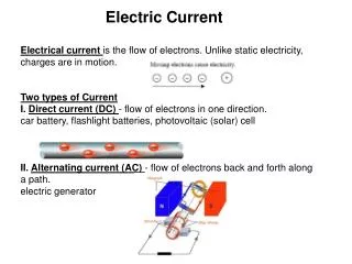
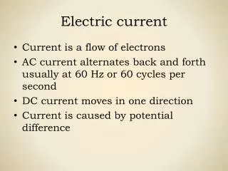
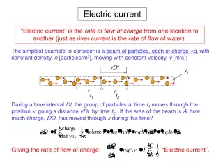
Electric current “Electric current” is the rate of flow of charge from one location to another (just as river current is the rate of flow of water). The simplest example to consider is a beam of particles, each of charge +q, with constant density, n [particles/m3], moving with constant velocity, v [m/s]: vDt A t1 t2 During a time interval Dt, the group of particles at time t1moves through the position x, going a distance vDt by time t2. If the area of the beam is A, how much charge, DQ, has moved through x during this time? Giving the rate of flow of charge: “Electric current”.
Electric current, continued More generally, we can define the electric current past a given location at a given time in terms of the instantaneous rate of charge flow: Electric current, I “ampere” And, in some problems, we may find that the charge concentration and/or velocity change across our collection area A. In this case we must define electric current density, J, and apply it as follows: Electric current density, J For a uniform beam of particles, the current density can be found by dividing I by A: What is the sign of I for different sign combinations of q and v?
Among the first people to understand electric current was… Luigi Galvani 1737-1798 Italian physician and physicist, who lived in Bologna. In 1771, he discovered that the muscles of dead frogs twitched when struck by a spark. He was a pioneer in modern obstetrics, and discovered that muscle and nerve cells produce electricity. Credited with the discovery of bioelectricity. iron copper
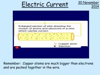
Electric current in a conductor All of these pictures show a current in a wire (conductor) traveling to the right. You may be surprised to see that there is an electric field, E, inside the conductor, “driving” the flow of particles. But our “E = 0” rule for conductors does not apply here since these charges are in motion, not in electrostatic equilibrium! Notice that we could “add” the top two diagrams to describe a current 2I, with no excess charge—the conductor would be neutral. When we looked at particle beams, there was no electric field. The particles were freely moving at constant velocity. We’ve also said that electrons are “free to move” inside conductors. So, since F = ma = qE, why aren’t the electrons accelerating? They are shown moving at constant velocity, vd !
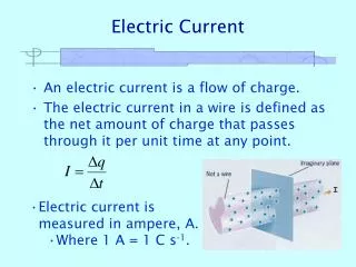
Electrons in a conductor are in thermal motion constantly colliding with the atoms/molecules The “free” (valence) electrons inside a conductor are not in free particle motion. After traveling some short distance, characterized by a “mean free path”, l, they will collide with an atom, rebounding in some random direction. The trajectory of a single electron will be a “random walk”, also known as “Brownian motion.” The net velocity averages to zero after many collisions. But when there is an electric field in the conductor, we see the motion at right. Between collisions, the electrons accelerate due to E, and each collision transfers energy to an atom. The electron has a net “drift velocity” to the right, vd.
Taking the drift velocity into account in our equations This involves almost no effort on our part. For any equation where we had velocity v, we now simply change it to vd. For a uniform flow of current carriers in a conductor: and Examples
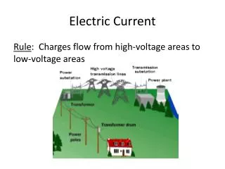
How is an electric field maintained inside a conductor? By surface charge on the outside of the conductor: Notice that the left end of the wire is at higher electric potential than the right end. There must be a “battery” or some other voltage source in the circuit to provide this. In this section of wire, the voltage difference between A and D would be DV = -EdAD.
Following the energy flow… You may have noticed that the electric field is doing work on the electrons. In the picture on the previous page, as each electron moves from D to A, it is acquiring kinetic energy K = qDV. Collisions with atoms/molecules transfer this kinetic energy to the bulk of the material, raising its temperature. The energy is then lost from the system in the form of heat. This situation is very similar to heat loss due to friction in mechanical systems. If standard conductors were perfect, there would be no energy loss. (They would be “superconductors”). This energy-loss property of conductors is known as “electrical resistivity”, r.
Resistivities and Temperature Coefficients for various materials metals semiconductors insulators
Ohm’s Law George Simon Ohm 1789-1854 German physicist who is famous for defining the fundamental relationship among voltage, current, and resistance through Ohm's Law. In 1826, Ohm discovered that the electric field required to maintain a given current density in a material is proportional to the current density. The proportionality constant is r, the resistivity of the material: Units: This “law” is really an approximation that works very well for many materials. 1 Ohm = 1 V/A = 1 W = 1 Omega (alliterative)
Resistivity, Resistance, and Resistors The next circuit element we will introduce is the “resistor” a two terminal device that intentionally adds electric resistance to a given path in a circuit. Let’s choose a cylindrical piece of material with resistivity r, and with the dimensions shown at left, and construct the resistor shown above. We can find the voltage across it by multiplying E by L. Then we press ahead to put the right hand side in terms of the current, I, and other constants: with “R” is the “resistance” of this piece of material when the terminals are connected to the areas at each end. Let’s check the units of R: So resistance has units of Ohms, and the most “useful” form of Ohm’s Law is V = RI.
Resistors, and some consequences of Ohm’s Law with The equations above tell us how to build a resistor with the desired R: choose a practical material, machine it to a length and area that gives the right ratio L/A, and attach two conducting terminals that connect to the whole endface at each end (so that each end surface is an equipotential). We can also use the equation for R to get a feeling for how several identical resistors behave when they are connected in series or in parallel. Sketch and discuss. Finally, if we are introducing resistors as circuit elements, we will need a symbol for them. Here it is:
Resistivity depends slightly on temperature Materials obeying Ohm’s Laws have a resistivity r associated with them, and are called “ohmic”. But in real materials, the resistivity will rise slowly with increasing temperature (metals), or fall slowly (semiconductors). The resistivities are measured at a reference temperature, such as 20o C, and the temperature correction is parameterized as a linear function with a being the “temperature coefficient”, with units 1/oC. Or, since resistance is proportional to resistivity: Example
Resistor construction, values, and color codes The most common type of resistor in use today is the carbon composition resistor. It is made from a solid rod of conductive material created by mixing carbon with an insulating ceramic filler. By changing the ratio of carbon to filler, the resistivity of the material can be adjusted from values close to that of pure carbon, up to very high resistivities. Samples and examples. Also show wire-wound resistors and variable resistors.
Ohmic: I=V/R Non-ohmic Non-ohmic I vs. V for various circuit devices metals, semiconductors, insulators vacuum diode silicon diode metals semiconductors superconductors Perfect conduction below critical temperature. Temperature dependence of r, or R,for various devices
A thermistor is a type of resistor used to measure temperature changes, relying on the change in its resistance with changing temperature. Thermistor is a combination of the words thermal and resistor. The Thermistor was invented by Samuel Ruben in 1930, and has U.S. Patent #2,021,491. If we assume that the relationship between resistance and temperature is linear (i.e. we make a first-order approximation), then we can say that: ΔR = kΔT where ΔR = change in resistance, ΔT = change in temperature, and k = first-order temperature coefficient of resistance. Thermistors can be classified into two types depending on the sign of k. If k is positive, the resistance increases with increasing temperature, and the device is called a positive temperature coefficient (PTC) thermistor, Posistor. If k is negative, the resistance decreases with increasing temperature, and the device is called a negative temperature coefficient (NTC) thermistor. Resistors that are not thermistors are designed to have the smallest possible k, so that their resistance remains almost constant over a wide temperature range. Wikipedia: Thermistor Symbol
Some electrical circuit symbols We’ve encountered three of these already (C, R, and conductor). More to come… C Capacitor (stores charge at its location in the circuit) L Inductor (resists changes in current through it)
The action of an ideal battery or power supply, placed in the simplest possible circuits An ideal battery is a voltage source with DV between its terminals, that maintains its potential difference independent of the current passing through it. What happens if we connect such a source to each of the circuit elements we have studied? We looked at this circuit already. When the battery is connected to the capacitor, current briefly flows through the battery until the potential difference across the capacitor equals that across the battery: V=Q/C. capacitor circuit + +Q V C -Q In this resistor circuit, current I keeps flowing around the circuit, through the wires and the two circuit elements. For a given battery voltage, the resistor determines the current. Ohm’s Law tells us: I=V/R. resistor circuit I + V V R This is all very tidy except for one thing. In the second circuit, as the resistance R is decreased to zero, the current goes to infinity. We know that real batteries don’t act this way, so we will need a more realistic description.
Real batteries have internal resistance Batteries are essentially electrochemical devices. The materials that make them up have resistance of their own, so circuit behavior can only be understood in detail by including this factor. I + In the tan box, we have modeled the more realistic battery as an ideal voltage source in series with an internal resistance, r. We now analyze the circuit including this resistance. V R r We will solve this using path independence. If we start at the top of the battery, and travel around the circuit, the voltage will drop by IR as we pass through the external resistor, by Ir through the internal resistor, and then it will rise by V through the voltage source—to the point where we began. So the sum of voltage changes around this path is zero: Discuss
“emf”, “electromotive force”, It is conventional when labeling the potential difference due to a voltage source to label it with a script , as shown below, and to call it “electromotive force”. But this practice is becoming less common because (1) it is hard to find this character in standard font sets, and (2) this is an electric potential difference, not a force. So in this course we will continue to label voltage sources with a “V”. R I + r Nevertheless, we will occasionally run into the term “emf” in upcoming chapters, especially in the form “induced emf”. It will still mean simply a difference in electric potential, and can be labeled as “V”, or “DV”.
A typical electrochemical cell The metallic conductors, copper and zinc, are immersed in an electrolyte that is filled with positively and negatively charged ions. Zinc is more electronegative than copper, and ends up with an excess of electrons. It becomes the negative terminal (“cathode”) of the cell, and the copper becomes the positive terminal (anode). This cell has a fixed potential difference, V, of about 1.5 V. Cells may be connected in series to produce a “battery”, with multiples of this voltage: 6, 9, 12, being common. (Technically, one cell alone is not a “battery.)
There are many types of batteries now available Disposable batteries: Zinc-carbon Zinc-chloride Zinc-air Alkaline Silver-oxide Lithium Mercury Water-activated Rechargeable batteries Lead-acid Lithium-ion Lithium-ion polymer Sodium-sulfate Nickel-iron Nickel metal hydride Nickel-cadmium Nickel-zinc Molten salt In disposable batteries, the electrolyte is depleted of ions as the battery operates. In rechargeable batteries, the chemical reactions involved can be reversed if charging voltage is applied, restoring the original densities of chemical reactants.
Energy and power in electric circuits Batteries may be used to provide power to a circuit, and resistive devices will dissipate that power. Recall that power, P, is the rate at which work is being done—or, by the work-energy theorem, the rate at which energy is being produced or used. The unit of power is the Watt (W). If a given circuit device has a voltage difference V across its terminals, and a current I is passing through it, we can calculate the power being produced or used as follows: Start with the definition of current: Multiply this equation by V, then notice that VdQ is the change in potential energy dU, of charge dQ passing through a voltage change V: Which gives us the very simple result:
Other convenient forms of the power equation Repeated application of V = RI will give two other forms of the power equation which may be more convenient for some problems, depending on the givens. Examples
Measuring voltage differences and currents In the table of circuit symbols, we encountered these two: An ideal voltmeter or ammeter must not disturb the circuit it is measuring. This has implications for their internal resistances. Suppose we add these meters to the basic battery-resistor circuit: The voltmeter has been connected in parallel with the resistor, to measure DV across its terminals. To avoid drawing any current through itself, the voltmeter must have infinite resistance. I + V R V A The ammeter has been inserted in the circuit, in order to measure the full current in the circuit path. To avoid introducing an additional voltage drop, the ammeter must have zero resistance. Real meters can, at best, get “very close” to perfection.
Currents at junctions As we’ve been analyzing problems, we’ve already been using the principle of charge conservation. For example, when two capacitors are connected in parallel, we have been writing Q = Q1 + Q2to indicate that the total charge put into the circuit is the sum of charges on the capacitors. If we now consider current, the flow of charge, the same conservation applies: currents are conserved at junctions. In the cases shown here, we might write I = I1 + I2for the top picture, and I1 + I2 = I.