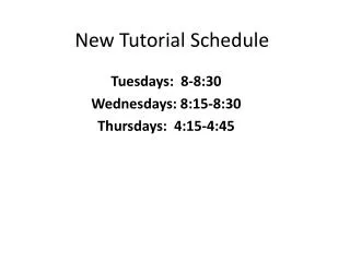
Tutorial schedule changes
Tutorial schedule changes. Original schedule: cam follower displacement diagram --March 13,2014 cam profiles -- March 20,2014 Ordinary gear trains -- March 27,2014 Current schedule : cam follower displacement diagram cam profiles


Tutorial schedule changes
E N D
Presentation Transcript
Tutorial schedule changes • Original schedule: • cam follower displacement diagram --March 13,2014 • cam profiles --March 20,2014 • Ordinary gear trains --March 27,2014 • Current schedule: • cam follower displacement diagram • cam profiles • ordinary gear trains --March 17,2014 March 27,2014 is cancelled March 13,2014
Figure 7.6 Disc cam mechanisms [Model 7.6]. Mechanics of Machines Cleghorn
Three types of follower motion Cycloidal : acceleration is zero at the beginning and end of motion Parabolic: constant acceleration Simple harmonic: a sine wave motion
Angular velocity: 60 rpm0-120 degree Cycloidal lift is 50mm120-180 degree dwell180-300 degree Cycloidal 300-360 degree dwell (a) Sketch the resulting displacement, velocity, and acceleration curves for 360° of cam rotation
Lift Displacement: cycloidal, period is four time than acceleration’s Velocity: period is double than acceleration’s Acceleration: sine wave Figure 7.17 Comparison of displacement, velocity, and acceleration for follower motions. Mechanics of Machines Cleghorn
A cam is required such that the follower rises 50 mm in 120° of cam rotation, dwells for 60°, returns in 120°, and dwells for 60°. The cam angular velocity is constant at 60rpm. The requirements are displayed in Fig. P6.17. (b) Determine the maximum follower velocity ( in mm/sec)
θ* is the angle when the velocity /acceleration is the maximum Β is the angle for the lift/return duration L is the lift distance Figure 7.16 Cycloidal motion. Mechanics of Machines Cleghorn
A cam is required such that the follower rises 50 mm in 120° of cam rotation, dwells for 60°, returns in 120°, and dwells for 60°. The cam angular velocity is constant at 60rpm. The requirements are displayed in Fig. P6.17. (c) Determine the maximum follower acceleration ( in mm/sec2)
A cam is required such that the follower rises 50 mm in 120° of cam rotation, dwells for 60°, returns in 120°, and dwells for 60°. The cam angular velocity is constant at 60rpm. The requirements are displayed in Fig. P6.17. (d) What is the magnitude of the displacement at 220° of cam rotation?
A cam is required such that the follower rises 50 mm in 120° of cam rotation, dwells for 60°, returns in 120°, and dwells for 60°. The cam angular velocity is constant at 60rpm. The requirements are displayed in Fig. P6.17. (d) Are there infinite spikes in the jerk profile? If so, at what locations? No
CAM profiles • Base circle diameter: 30 mm • Offset: 0 • Roller diameter: 10 mm • Angular velocity: 10rad/s • 0-120 degree SHM lift is 10mm • 120-270 degree dwell • 270-360 degree parabolic • Plot cams with three kinds of followers---knife edge, flat face, roller.
CAM design steps: • 1 Specify the displacement diagram, base circle diameter, and follower type. • 2. Draw the displacement diagram. a) Draw the prime circle tangent to the zero follower displacement axis. The position of the follower at 0 is known as the home position. Home position Prime circle
b) Divide the displacement diagram in several intervals. Six intervals: 0-40; 40-80; 80-120; 120-300; 300-330; 330-360 c) Divide the prime circle in the same number of intervals as the displacement diagram. 3. Draw parallel lines from the displacement diagram to the follower home position. Each line represents the rise of the follower at that specific interval.
4. Invert the mechanism, fix the cam and move the follower around the cam in the opposite direction to the cam rotation. This is done by drawing circles about the centre of the prime circle, the radius at each circle are the displacements of the follower. 5. Draw the cam profile inside the envelope of the follower displacements 330 40 80 300 270 120
Flat face follower: Draw lines which are tangent to follower displacement circles
Extend the tangent lines and make them intersect. Connect the midpoints using spline lines to get the cam profile
Roller follower: Home position is the centre of the roller. The prime circle is tangent to the roller.
Make sure the connect line is tangent with both roller circles.