PROBLEM-1
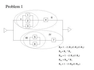
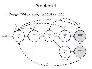
P 2 = 8 kN. P 1 = 5 kN. C. B. A. D. 2 m. 2 m. 2 m. 6 m. P 2 = 8 kN. P 1 = 5 kN. B. C. A. D. D y (6) – P 2 (4) – P 1 (2) = 0. A y. D y. 2 m. 2 m. 2 m. D y = (32 + 10)/6 = 7 kN. A y – P 1 – P 2 + D y = 0. A y = P 1 + P 2 – D y = 6 kN. PROBLEM-1.

PROBLEM-1
E N D
Presentation Transcript
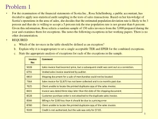
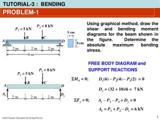
P2 = 8 kN P1 = 5 kN C B A D 2 m 2 m 2 m 6 m P2 = 8 kN P1 = 5 kN B C A D Dy(6) – P2(4) – P1(2) = 0 Ay Dy 2 m 2 m 2 m Dy = (32 + 10)/6 = 7 kN Ay– P1– P2+ Dy = 0 Ay =P1 + P2 – Dy = 6 kN PROBLEM-1 Using graphical method, draw the shear and bending moment diagrams for the beam shown in the figure. Determine the absolute maximum bending stress. 5cm 8cm FREE BODY DIAGRAM and SUPPORT REACTIONS MA = 0; Fy = 0;
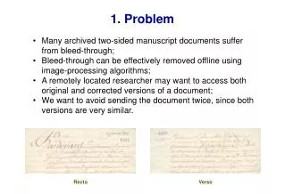
P2 = 8 kN P1 = 5 kN B C A D Ay Dy 2 m 2 m 2 m PROBLEM-1 SHEAR FORCE DIAGRAM SHEAR FORCE AREA: V (kN) A1 = (6)(2) = 12 kN.m 6 A2 = (1)(2) = 2 kN.m A2 A1 A3 = (–7)(2) = –14 kN.m 1 A3 –7
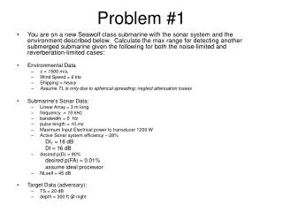
P2 = 8 kN P1 = 5 kN B C A D Ay Dy 2 m 2 m 2 m PROBLEM-1 BENDING MOMENT DIAGRAM 5cm M0 = 0 8cm M2 =M0 + A1 = 0 + 12 = 12 kN.m = 12 + 2 = 14 kN.m M4 =M2 + A2 M (kN.m) 14 M6 =M4 + A3 = 14 – 14 = 0 12 Absolute maximum bending stress: D A B C
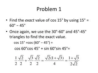
P1=10 kN P2=15 kN 2 m 2 m 2 m 6 m P1=10 kN P2=15 kN 2 m 2 m 2 m Cy Ay PROBLEM-2 If the rod bar has a diameter of 100 mm, Determine the absolute maximum bending stress in the shaft. A B C FREE BODY DIAGRAM and SUPPORT REACTIONS A B C MA = 0; P1(2) – P2(2) + Cy(4) = 0 Cy = (30 – 20)/4 = 2.5 kN Fy = 0; Ay– P1 – P2 + Cy = 0 Ay = 22.5 kN
12.5 A2 A3 -2.5 A1 -10 PROBLEM-2 P1=10 kN P2=15 kN SHEAR FORCE DIAGRAM 2 m 2 m 2 m Ay = 22.5 kN Cy = 2.5 kN SHEAR FORCE AREA: V (kN) A1 = (–10)(2) = –20 kN.m A2 = (12.5)(2) = 25 kN.m A3 = (–2.5)(2) = –5 kN.m
5 -20 PROBLEM-2 P1=10 kN P2=15 kN BENDING MOMENT DIAGRAM M0 = 0 M2 =M0 + A1 2 m 2 m 2 m = 0 – 20 = –20 kN.m Ay = 22.5 kN Cy = 2.5 kN M4 =M2 + A2 M (kN.m) = –20 + 25 = 5 kN.m M6 =M4 + A3 = 5 – 5 = 0 Absolute maximum bending stress:
A B By Ay 8 kN Ay = 12 + 8 – By 12 kN EXAMPLE-3 If the shaft has a diameter of 50 mm, Determine the absolute maximum Bending stress in the shaft. Reaction forces: MA = 0; Fy = 0; Free-body diagram Ay = 19.75 kN
A B 0.25 kN 8 kN 19.75 kN 12 kN 0.25 m 0.4 m 0.4 m M 0.1 kN.m x –3 kN.m EXAMPLE-3 Bending moment diagram: M0 = 0 M0.25 = –12x0.25 = –3 kN.m M0.65= (–12x0.65)+(19.75x0.4)=0.1 kN.m M1.05 = 0 Absolute maximum bending stress:
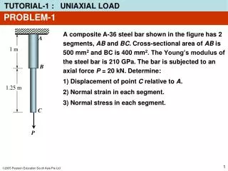
PROBLEM-4 Shaft is supported by smooth journal bearings at A and B. Due to transmission of power to and from the shaft, the belts on the pulleys are subjected to the tensions shown. Determine the smallest diameter of the shaft using the maximum-shear-stress theory, with allow = 50 MPa.
PROBLEM-4 Support reactions are calculated and shown on the free-body diagram of the shaft.
EXAMPLE 11.6 (SOLN) z x Bending-moment diagrams for Mx and Mz are shown above. y y MA2 = 0 MA1 = 0 MC2 = (150)(0.250) = 37.5 N.m MC1 = (475)(0.250) = 118.75 N.m MB2 = (150)(0.50) = 75 N.m
EXAMPLE 11.6 (SOLN) Torque diagram is also shown.
EXAMPLE 11.6 (SOLN) By inspection, critical pts for bending moment occur either at C or B. Also, just to the right of C and at B the torsional moment is 7.5 N·m. Moment at B is At C, resultant moment is
EXAMPLE 11.6 (SOLN) Since the design is based on the maximum-shear-stress theory, Eqn 11-2 applies. The radical √(M2 + T2) will be the largest at section just to the right of C. We have Thus the smallest allowable diameter is
W W/2 = 175L W/2 = 175L PROBLEM-8 Determine the length of the length of the center portion of the bar so that the maximum bending stress at section A, B, and C is the same. The bar has a thickness of 10 mm. Reaction forces: Since the total weight is located in the middle of beam, the support reaction has the same value; W/2 = (350L)/2 = 175L Free-body diagram
PROBLEM-8 Stress concentration factor: Referring to the graph: K = 1.45
W/2 VA VC MA MC W/2 = 175L W/2 = 175L Reaction forces: W W/2 = 175L W/2 = 175L PROBLEM-8 Free-body diagram for analyzing the bending moment at A, B, and C: Bending moment at section A: Bending moment at section C: MC = (175L)(0.3+L/2) – (175L)(L/4) MA = (175L)(0.3) = 52.5 L = 52.5 L + 43.75 L2 MB = MA = 52.5 L (symmetry) Bending moment at section B:
PROBLEM-8 Maximum bending stress at sections A, B, and C At either section A or B: At section C: Solving smax)A = smax)Cwill yield : L = 2.715 m