Download
1 / 25
250 likes | 449 Vues
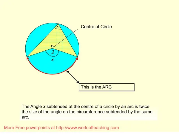
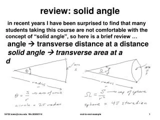
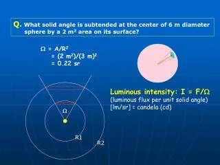
W. R1. R2. Q. What solid angle is subtended at the center of 6 m diameter sphere by a 2 m 2 area on its surface?. W = A/R 2 = (2 m 2 )/(3 m) 2 = 0.22 sr. Luminous intensity: I = F/ W (luminous flux per unit solid angle) [lm/sr] = candela (cd). 3 m 2. 10 m.

E N D
W R1 R2 Q. What solid angle is subtended at the center of 6 m diameter sphere by a 2 m2 area on its surface? W = A/R2 = (2 m2)/(3 m)2 = 0.22 sr Luminous intensity: I = F/W (luminous flux per unit solid angle) [lm/sr] = candela (cd)
3 m2 10 m Q. A spotlight is equipped with a 30 cd bulb. This light beams onto a vertical wall in a circular shape with 3 m2 area. The spotlight is 10 m from the wall. Calculate the luminous intensity for the spotlight. Total luminous flux coming out of the bulb, F = I 4p = (30 cd)(4p sr) = 377 lm This amount of luminous flux is concentrated on the 3 m2 spot. To get the luminous intensity, we need to know the solid angle that bright spot subtend. W = A/R2 = (3 m2)/(10 m)2 = 0.03 sr I (spot) = (377 lm)/(.03 sr) = 1.26 x 10⁴ cd
2 1 W R1 R2 Illuminance E = F/A Luminous flux per unit area [lm/m2] = Lux (lx) I1 = I2 However, E1 ≠ E2 E1 = F/A1 = F/(WR12), E2 = F/A2 = F/(WR22) W = A/R2
A q W = Acos/R2 I = F/W = F/(Acosq/R2) E = F/A E = Icos/R2 Relation between I (luminous intensity) and E (illuminance) I = F/W E = F/A W = A/R2 E = I/R2
q q Q. A 300 cd lamp is located 3 m from a surface with 0.25 m2 area. The luminous flux makes an angle of 30 deg with the normal to the surface. (a) What is the illuminance? (b) what is the luminous flux shining on the surface? • Flux thru the surface: f • f = I W W = A/R2 • = (0.25)cos30/32 • = 0.024 sr f = (300 cd)(0.024 sr) = 7.2 lm E = f/A = (7.2 lm)/(0.25 m2) = 28.8 lx
x z y E B Polarization + - For this type of EM wave, E field oscillates in a fixed direction, and so does B field. Linearly polarized!! Direction of E-field determines polarization direction: This wave is polarized in x-direction.
E Natural light is “unpolarized”. We can produce polarized light from unpolarized light!! Polaroid sheet allows light pass through inly if the E-field vector is in a specific direction.
For unpolarized light, a polaroid sheet reduces its intensity to half (sunglasses).
Chapter 26 Reflection and Refraction
A Brief History of Light • 1000 AD • It was proposed that light consisted of tiny particles • Newton • Used this particle model to explain reflection and refraction • Huygens • 1670 • Explained many properties of light by proposing light was wave-like
A Brief History of Light, cont • Young • 1801 • Strong support for wave theory by showing interference • Maxwell • 1865 • Electromagnetic waves travel at the speed of light
A Brief History of Light, final • Planck • EM radiation is quantized • Implies particles • Explained light spectrum emitted by hot objects • Einstein • Particle nature of light • Explained the photoelectric effect
Geometric Optics – Using a Ray Approximation • Light travels in a straight-line path in a homogeneous medium until it encounters a boundary between two different media • The ray approximation is used to represent beams of light • A ray of light is an imaginary line drawn along the direction of travel of the light beams
Ray Approximation • A wave front is a surface passing through points of a wave that have the same phase and amplitude • The rays, corresponding to the direction of the wave motion, are perpendicular to the wave fronts
Reflection of Light • A ray of light, the incident ray, travels in a medium • When it encounters a boundary with a second medium, part of the incident ray is reflected back into the first medium • This means it is directed backward into the first medium
Specular Reflection • Specular reflection is reflection from a smooth surface • The reflected rays are parallel to each other • All reflection in this text is assumed to be specular
Diffuse Reflection • Diffuse reflection is reflection from a rough surface • The reflected rays travel in a variety of directions • Diffuse reflection makes the road easy to see at night
Law of Reflection • The normal is a line perpendicular to the surface • It is at the point where the incident ray strikes the surface • The incident ray makes an angle of θ1 with the normal • The reflected ray makes an angle of θ1’with the normal
Law of Reflection, cont • The angle of reflection is equal to the angle of incidence • θ1= θ1’
Specular Reflection Diffuse Reflection Reflection and Mirrors q1 = q1 q1 1 Law of reflection
|q| When we talk about an image, start from an ideal point light source. Every object can be constructed as a collection of point light sources. VIRTUAL IMAGE p Image forms at the point where the light rays converge. When real light rays converge Real Image When imaginary extension of L.R. converge Virtual Image Only real image can be viewed on screen placed at the spot.
VIRTUAL IMAGE p |q| For plane mirror: p = |q| How about left-right? Let’s check?
focal Point f: focal length = R/2 Spherical Mirror R: radius of curvature Optical axis concave convex Parallel light rays: your point light source is very far away. Focal point: (i) Parallel incident rays converge after reflection (ii) image of a far away point light source forms (iii) On the optical axis