Download
1 / 17
170 likes | 333 Vues
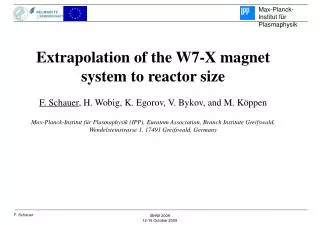
Extrapolation of the W7-X magnet system to reactor size F. Schauer , H. Wobig, K. Egorov, V. Bykov, and M. Köppen Max-Planck-Institut für Plasmaphysik (IPP), Euratom Association, Branch Institute Greifswald, Wendelsteinstrasse 1, 17491 Greifswald, Germany. CONTENT

E N D
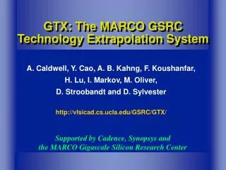
Extrapolation of the W7-X magnet system to reactor size F. Schauer, H. Wobig, K. Egorov, V. Bykov, and M. Köppen Max-Planck-Institut für Plasmaphysik (IPP), Euratom Association, Branch Institute Greifswald, Wendelsteinstrasse 1, 17491 Greifswald, Germany ISHW 2009 12-16 October 2009
CONTENT • HELIAS magnetic design with MODUCO • Coil cable • Coil winding pack • Magnet system structure • Electrical design • Conclusion ISHW 2009, 12-16 October 2009
MODUCO • (MODUlar COils) by H. Wobig • Features: • Central coil filament (CCF) is represented by 4-6 control points with tangent vectors • CCF is interpolated by cubic Beziér curves • Wendelstein 7-X field has been well reproduced with MODUCO • Classical stellarator and 3, 4 and 5 period reactor configurations can be reproduced • The code computes magnetic surfaces and particle orbits • Magnetic field within the WP and the forces on the coils can be computed • Further features are planned: • Computation of inductivity, magnetic energy, plasma currents, field ripple • Modelling of vacuum vessel and blanket, • Neutron wall load ISHW 2009, 12-16 October 2009
HSR50a Scaling 4 x W-7X Symmetry 5 Periods Coil number 50 Major radius 22 m B on axis 5.6 T B on coil 12.3 T Magnetic energy 152 GJ The magnetic field is isomorph to the Wendelstein 7-X field ISHW 2009, 12-16 October 2009
Comparison of ITER and HSR5 coils ITER toroidal field (TF) coil HSR50a coil #5 ISHW 2009, 12-16 October 2009
ITER coil key components TF coil conductor CS & PF coil conductor ITER TF coil inner leg section (plasma axis is at the left side) ISHW 2009, 12-16 October 2009
Comparison of ITER TF and HSR50a coils ISHW 2009, 12-16 October 2009
HSR50a winding pack (WP) options Square conductor concept Radial plate concept acc. to ITER CS and PF coils acc. to ITER TF coils ISHW 2009, 12-16 October 2009
HSR50a coil 1 central current filament in the „minimum coordinate“ system. ISHW 2009, 12-16 October 2009
HSR5 coils comparison Dimensions of the CCF in the „minimum coordinate system“ ISHW 2009, 12-16 October 2009
Radial plate (RP) of coil type 1Orientation wrt. the min. coord. system front view RP element long edges in true length side view RP element long edges are parallel the others top view ISHW 2009, 12-16 October 2009
HSR50a radial plate concept RP rib prototype for ITER ISHW 2009, 12-16 October 2009
Structural analysis Coil casing and inter-coil structure model ISHW 2009, 12-16 October 2009
Structural analysis Tresca stresses Weight support Module inboard side Module outboard side • Local stress peaks are partly acceptable; partly are due to rough interface modelling • Only a few stress peaks need to be eliminated during detail design • Allowable limits are: 625 MPa membrane; 810 MPa membrane plus bending stresses • Realistic material with 940 MPa yield limit assumed • At no place a steel plate thickness >150 mm required • Maximal deformation due to Lorentz forces is 60 mm only ISHW 2009, 12-16 October 2009
Electrical design Comparative estimates for coil fast discharge behaviour are performed with the following relations: Discharge voltage: Hot spot temperature: ( = equivalent discharge time constant, mi = mass per unit length) • Thermal capacities of electrical insulation and RP • Helium flow within the conductor • Secondary currents in RP and structure • Capacitances between the WP components • 3D-heat conduction within conductor and WP • Increasing resistivity of the discharge resistors Not considered are: ISHW 2009, 12-16 October 2009
Electrical design simplified analysis results *) is the switch-off time delay • All coils in series with one power supply • Fast discharge unit after every other coil • 25 pairs of current leads Electrical layout: ISHW 2009, 12-16 October 2009
Conclusion • A 5-periodic HELIAS reactor with ~12 T at the coil and 5.5 T at the plasma axis can be built • The basic physics can be directly taken over from W7-X • Quasi existing ITER key technologies need only to be adapted to a HSR5 magnet system • For further development work a professional full-time engineering team has to be installed • 3- and 4-periodic HELIAS versions have to be considered too as options • Final design decisions will be influenced by the outcome of the W7-X experiments ISHW 2009, 12-16 October 2009