A TinyOS Sensor Application called MyApp
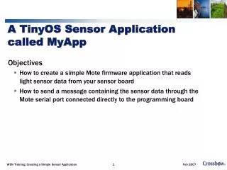
A TinyOS Sensor Application called MyApp. Objectives How to create a simple Mote firmware application that reads light sensor data from your sensor board How to send a message containing the sensor data through the Mote serial port connected directly to the programming board.

A TinyOS Sensor Application called MyApp
E N D
Presentation Transcript
A TinyOS Sensor Application called MyApp Objectives How to create a simple Mote firmware application that reads light sensor data from your sensor board How to send a message containing the sensor data through the Mote serial port connected directly to the programming board WSN Training: Creating a Simple Sensor Application
Required Hardware and PC Setup • Two MICA Motes: standard editions of MICA2 (MPR4x0) or MICAz (MPR2600) or OEM editions of MICA2 or MICAz • One sensor or data acquisition board: MDA100, MTS300 or MTS310 • One gateway board: MIB510, MIB520, or MIB600 and the associated hardware (cables, power supply) for each • A Windows PC with MoteWorks installed • The steps that you’ll take to build the application will be as follows: • Build (compile) and download the application • Take a closer look at the code and auxiliary files WSN Training: Creating a Simple Sensor Application
About sensor application MyApp • What does MyApp do? • It is a simple sensing application that samples the light sensor—the photodetector—on a sensor board, packetizes the data, and sends the data back to the base station. • What am I expected to learn? • This exercise is intended to is presented here to help further familiarize you with nesC programming and TinyOS messaging. • What is different from the app MyApp in lesson_1 ? • Take light readings using one of the following sensors boards: MTS300/310 or MDA100 • Use the Mote serial port (UART) and radio to send sensor data to the base station • Blink the green LED when the sensor is sampled • Blink the yellow LED when the sensor data message is successfully sent to the base station • Compile and debug if necessary WSN Training: Creating a Simple Sensor Application
MyApp Application Review • The application folder (directory) is where all your top-level application code and associated files will be stored. • Navigate to the directory /MoteWorks/apps/tutorials/lesson_ 2 • The Makefile and Makefile.component are exactly the same as the MyApp of lesson_1 application so we will move along to the configuration and module files. WSN Training: Creating a Simple Sensor Application
Sensor Application MyApp_Sensor • What’s new? • The sensorboardsApp.h file • What is it used for? • Define packet structure • Defines the XSensor header • Defines the sensor data payload • So you can understand what the bytes mean in a serial data stream • Defines the default values for critical fields • SENSOR_BOARD_ID • “Tags” the packet so XServe can identify what application sent it. • Sensor data packets are put into the proper database table or flat file by XServe WSN Training: Creating a Simple Sensor Application
MyApp Steps Makefile Makefile.component Top-level application configuration Top-level module Compile app and flash Motes nesC Auto documentation WSN Training: Creating a Simple Sensor Application
MyApp – Makefile.component • Specify the sensorboard in the Makefile.component file • For example, the Makefile.component for MyApp is • What does this do? • Tells the nesC compiler to link in all the TinyOS components (drivers) required to access the sensors on the MTS310 sensorboard. • Drivers for the MTS310 sensorboard are located in the /MoteWorks/tos/sensorboards/mts310 folder. • NOTE: There are drivers for other sensorboards located in under /MoteWorks/tos/sensorboards. COMPONENT=MyApp SENSORBOARD=mts310 WSN Training: Creating a Simple Sensor Application
Review: MyApp Steps Makefile Makefile.component Top-level application configuration Top-level module Compile app and flash Motes nesC Auto documentation WSN Training: Creating a Simple Sensor Application
nesC Keywords – Implementation WSN Training: Creating a Simple Sensor Application
/MoteWorks/apps/tutorials/lesson_2/MyApp.nc Configuration – Sampling the Light Sensor • includes sensorboardApp; • /** • * This module shows how to use the Timer, LED, ADC and Messaging • * components. • * Sensor messages are sent to the serial port • **/ • configuration MyApp { • } • implementation { • components Main, MyAppM, TimerC, LedsC, Photo, GenericComm as Comm; • Main.StdControl -> TimerC.StdControl; • Main.StdControl -> MyAppM.StdControl; • Main.StdControl -> Comm.Control; • MyAppM.Timer -> TimerC.Timer[unique("Timer")]; • MyAppM.Leds -> LedsC.Leds; • MyAppM.PhotoControl -> Photo.PhotoStdControl; • MyAppM.Light -> Photo.ExternalPhotoADC; • MyAppM.SendMsg -> Comm.SendMsg[AM_XSXMSG]; • } NEW! The Photo component is used to actuate the sensorboard photo sensor device. NEW! TheGenericComm component is used to send messages over the serial port and radio. WSN Training: Creating a Simple Sensor Application
MyApp.nc Configuration – Sampling the Light Sensor • includes sensorboardApp; • /** • * This module shows how to use the Timer, LED, ADC and Messaging • * components. • * Sensor messages are sent to the serial port • **/ • configuration MyApp { • } • implementation { • components Main, MyAppM, TimerC, LedsC, Photo, GenericComm as Comm; • Main.StdControl -> TimerC.StdControl; • Main.StdControl -> MyAppM.StdControl; • Main.StdControl -> Comm.Control; • MyAppM.Timer -> TimerC.Timer[unique("Timer")]; • MyAppM.Leds -> LedsC.Leds; • MyAppM.PhotoControl -> Photo.PhotoStdControl; • MyAppM.Light -> Photo.ExternalPhotoADC; • MyAppM.SendMsg -> Comm.SendMsg[AM_XSXMSG]; • } The Photo component implements the StdControl interface for turning on and off the light sensor and the ADC interface for sampling the sensor value through the hardware ADC port. WSN Training: Creating a Simple Sensor Application
MyApp.nc Configuration – Sampling the Light Sensor • includes sensorboardApp; • /** • * This module shows how to use the Timer, LED, ADC and Messaging • * components. • * Sensor messages are sent to the serial port • **/ • configuration MyApp { • } • implementation { • components Main, MyAppM, TimerC, LedsC, Photo, GenericComm as Comm; • Main.StdControl -> TimerC.StdControl; • Main.StdControl -> MyAppM.StdControl; • Main.StdControl -> Comm.Control; • MyAppM.Timer -> TimerC.Timer[unique("Timer")]; • MyAppM.Leds -> LedsC.Leds; • MyAppM.PhotoControl -> Photo.PhotoStdControl; • MyAppM.Light -> Photo.ExternalPhotoADC; • MyAppM.SendMsg -> Comm.SendMsg[AM_XSXMSG]; • } • MyAppM.PhotoControl (StdControl interface) to the Photo.PhotoStdControl (StdControl interface for the light sensor) • The MyAppM.Light (ADC interface) to the • Photo.ExternalPhotoADC (ADC interface for light sensor). WSN Training: Creating a Simple Sensor Application
MyApp.nc Configuration – Sampling the Light Sensor • includes sensorboardApp; • /** • * This module shows how to use the Timer, LED, ADC and Messaging • * components. • * Sensor messages are sent to the serial port • **/ • configuration MyApp { • } • implementation { • components Main, MyAppM, TimerC, LedsC, Photo, GenericComm as Comm; • Main.StdControl -> TimerC.StdControl; • Main.StdControl -> MyAppM.StdControl; • Main.StdControl -> Comm.Control; • MyAppM.Timer -> TimerC.Timer[unique("Timer")]; • MyAppM.Leds -> LedsC.Leds; • MyAppM.PhotoControl -> Photo.PhotoStdControl; • MyAppM.Light -> Photo.ExternalPhotoADC; • MyAppM.SendMsg -> Comm.SendMsg[AM_XSXMSG]; • } • This wires the XSensor channel of GenericComm into the application’s send interface. WSN Training: Creating a Simple Sensor Application
Review: MyApp Steps Makefile Makefile.component Top-level application configuration Top-level module Compile app and flash Motes View data via XServe WSN Training: Creating a Simple Sensor Application
Creating the Top Level Module • The application’s module is located in the MoteWorks/apps/tutorials/lesson_2/MyAppM.nc file. • How does this module differ from MoteWorks/apps/tutorials/lesson_1/MyAppM.nc? • This new module differs from the MoteWorks/apps/tutorials/lesson_1/MyAppM.nc module in that it adds the functionality of sampling the light sensor when the timer fires • Then a sensor message is sent through the Mote’s serial (UART) port when the sampling is complete. • (Radio communications will be done in the another session) WSN Training: Creating a Simple Sensor Application
nesC Keywords – Implementation WSN Training: Creating a Simple Sensor Application
MyAppM.nc – Specification • Hardware specific definitions for the MTS300/310. • Located in the application directory • includes sensorboardApp; • /** • * This module shows how to use the Timer, LED, ADC and Messaging • * components • * Sensor messages are sent to the serial port • **/ • module MyAppM { • provides { • interface StdControl; • } • uses { • interface Timer; • interface Leds; • interface StdControl as PhotoControl; • interface ADC as Light; • interface SendMsg; • } • } WSN Training: Creating a Simple Sensor Application
MyAppM.nc – Implementation • implementation { • bool sending_packet = FALSE; • TOS_Msg msg_buffer; • XDataMsg *pack; • /** • * Initialize the component. • * • * @return Always returns <code>SUCCESS</code> • **/ • command result_t StdControl.init() { • call Leds.init(); • call PhotoControl.init(); • // Initialize the message packet with default values • atomic { • pack = (XDataMsg *)&(msg_buffer.data); • pack->xSensorHeader.board_id = SENSOR_BOARD_ID; • pack->xSensorHeader.packet_id = 2; • pack->xSensorHeader.node_id = TOS_LOCAL_ADDRESS; • pack->xSensorHeader.rsvd = 0; • } • returnSUCCESS; • } WSN Training: Creating a Simple Sensor Application
nesC Keywords – Implementation WSN Training: Creating a Simple Sensor Application
atomic Keyword (Review) • atomickeyword is used to denote a block of code that runs uninterrupted (interrupts disabled) • Prevents race conditions • When should it be used? • Required to update global variables that are referenced in async event handlers • Must use atomic block in all other functions and tasks where variable is referenced • nesC compiler with generate warning messages for global variables that need atomic blocks • Example: SensorAppM.nc:44: warning: non-atomic accesses to shared variable ‘voltage’ WSN Training: Creating a Simple Sensor Application
interface ADC { async command result_t getData(); async command result_t getContinuousData(); async event result_t dataReady(uint16_t data); } The ADC interface is specified with two commands: getData getContinuousData and one event dataReady What to do to sample the thermistor sensor? call the getData command This will start a process of sampling the light sensor through the processor hardware ADC interface At some later time this process will complete and receive the current light sensor value through the dataReady event nesC Interface -- ADC WSN Training: Creating a Simple Sensor Application
event result_t Timer.fired() { call Leds.redToggle(); call PhotoControl.start(); call Light.getData(); … async event result_t Light.dataReady(uint16_t data) { atomic pack->xData.datap1.light = data; atomic pack->xData.datap1.vref = 417; // a dummy 3V reference voltage, 1252352/3000 = 417 post SendData(); call Leds.yellowToggle(); … The Timer.fired() event function we first turn on the light sensor by calling the start() command through the StdControl interface. The red LED will blink (“heartbeat”) when this happens. Next we call the getData() command through the ADC interface to start the process of sampling the current tvalue. At some time in the near future when the sampling has completed we then receive a callback in the form of a dataReady() event. Sample Sensor and Call Back with Value 1 2 3 WSN Training: Creating a Simple Sensor Application
event result_t Timer.fired() { call Leds.redToggle(); call PhotoControl.start(); call Light.getData(); … async event result_t Light.dataReady(uint16_t data) { atomic pack->xData.datap1.light = data; atomic pack->xData.datap1.vref = 417; // a dummy 3V reference voltage, 1252352/3000 = 417 post SendData(); call Leds.yellowToggle(); … The dataReady() event passes the 16-bit (10 significant bits) photodetector value that we store in our message packet for sending later. The last thing we do is to post a task (a split-phase operation) to send a message containing the sensor data and fire the yellow LED Sample Sensor and Call Back with Value 5 4 WSN Training: Creating a Simple Sensor Application
nesC Keywords – Implementation WSN Training: Creating a Simple Sensor Application
Non-blocking commands initiate an operation Continue/idle Event indicates completion at some future time Split-Phase -- Request & Done Sequence Component1 Component2 commandA { … call Comp2.goCmdX; //continue return SUCCESS} goCmdX{ … post task1(); return SUCCESS} Task1{ //do stuff signal cmdXDone(); return SUCCESS} Event handler event cmdXDone{ //process result … return SUCCESS} TOS Scheduler WSN Training: Creating a Simple Sensor Application
When to Use Split-Phase • Variable duration processes • Hardware I/O operations • ADC start conversion –> Data Ready • Slow devices • Flash memory, Write buffer –> Done • Asynchronous or Complex Processes • Send a message to communications stack and continue with operations until .sendDone WSN Training: Creating a Simple Sensor Application
Sending a Message Packet – GenericComm • How to send a packet of data to the outside world? • Use the TinyOS communication component named GenericComm. • GenericComm is able to send packets in two ways • The UART port or • Over the radio • How is that specified? • The destination node address specified • Reserved node addresses • Broadcast 0xFFFF • UART Channel 0x007E • Otherwise send directly to a specific node ID in it’s RF neighborhood WSN Training: Creating a Simple Sensor Application
implementation { components Main, MyAppM, TimerC, LedsC, Photo, GenericComm as Comm; Main.StdControl -> TimerC.StdControl; Main.StdControl -> MyAppM.StdControl; Main.StdControl -> Comm.Control; … MyAppM.SendMsg -> Comm.SendMsg[AM_XSXMSG]; … The GenericComm (aliased as Comm) is connected through its Comm.Control (StdControl) interface The MyAppM module connects to one instance of the Comm.SendMsg interface. The AM_XSXMSG identifies the active message type. This value is used to distinguish between multiple messages you may wish to send. MoteWorks/apps/tutorials/lesson_2/MyApp.nc Configuration Revisited WSN Training: Creating a Simple Sensor Application
interface SendMsg { command result_t send(uint16_t address, uint8_t length, TOS_MsgPtr msg); event result_t sendDone(TOS_MsgPtr msg, result_t success); } The SendMsg interface specifies one command Send and one event sendDone To send a message call the send command with the correct parameters A sendDone event is received after the message has been sent nesC Interface -- SendMsg WSN Training: Creating a Simple Sensor Application
interface SendMsg { command result_t send(uint16_t address, uint8_t length, TOS_MsgPtr msg); event result_t sendDone(TOS_MsgPtr msg, result_t success); } Each message that is sent using the SendMsg interface is defined by a data structure named TOS_Msg nesC Interface -- SendMsg WSN Training: Creating a Simple Sensor Application
typedef struct TOS_Msg { /* The following fields are transmitted/received on the radio. */ uint16_t addr; uint8_t type; uint8_t group; uint8_t length; int8_t data[TOSH_DATA_LENGTH]; } typedef TOS_Msg *TOS_MsgPtr; addr – the destination address type – the active message type (for this application it is AM_XSXMSG) group – group id specified during programming length – the payload length data – variable length payload area (sensor data) nesC Data Structure -- TOSMsg WSN Training: Creating a Simple Sensor Application
command result_t StdControl.init() { … // Initialize the message packet with default values atomic { pack = (XDataMsg *)&(msg_buffer.data); pack->xSensorHeader.board_id = SENSOR_BOARD_ID; pack->xSensorHeader.node_id = TOS_LOCAL_ADDRESS; pack->xSensorHeader.rsvd = 0; } … The data region in the TOS_Msg is where we place our application specific payload. The code excerpt above is from the MoteWorks/apps/tutorials/lesson_2/MyAppM.nc module that shows how we initialize the payload area of the TOS_Msg for our specific sensor application MoteWorks/apps/tutorials/lesson_2/MyAppM.nc – Application Data Payload WSN Training: Creating a Simple Sensor Application
void task SendData() { call PhotoControl.stop(); if (sending_packet) return; atomic sending_packet = TRUE; // send message to UART (serial) port if (call SendMsg.send(TOS_UART_ADDR,sizeof(XDataMsg),&msg_buffer) != SUCCESS) sending_packet = FALSE; … event result_t SendMsg.sendDone(TOS_MsgPtr msg, result_t success) { call Leds.greenToggle(); atomic sending_packet = FALSE; … MoteWorks/apps/tutorials/lesson_2/MyAppM.nc – Application Data Payload Notice first how the sendData task calls the stop command for the light sensor component. This is done in order to save power when we are not using the sensor. If we are currently in the process of sending a message (sending_packet = TRUE) we just return. This means the sendDone event has yet to be called and we must wait. WSN Training: Creating a Simple Sensor Application
void task SendData() { call PhotoControl.stop(); if (sending_packet) return; atomic sending_packet = TRUE; // send message to UART (serial) port if (call SendMsg.send(TOS_UART_ADDR,sizeof(XDataMsg),&msg_buffer) != SUCCESS) sending_packet = FALSE; … event result_t SendMsg.sendDone(TOS_MsgPtr msg, result_t success) { call Leds.greenToggle(); atomic sending_packet = FALSE; … MoteWorks/apps/tutorials/lesson_2/MyAppM.nc – Application Data Payload We call the SendMsg.send command passing the destination node address, in this case TOS_UART_ADDR and a pointer to the actual message packet we wish to send. WSN Training: Creating a Simple Sensor Application
void task SendData() { call PhotoControl.stop(); if (sending_packet) return; atomic sending_packet = TRUE; // send message to UART (serial) port if (call SendMsg.send(TOS_UART_ADDR,sizeof(XDataMsg),&msg_buffer) != SUCCESS) sending_packet = FALSE; … event result_t SendMsg.sendDone(TOS_MsgPtr msg, result_t success) { call Leds.greenToggle(); atomic sending_packet = FALSE; … MoteWorks/apps/tutorials/lesson_2/MyAppM.nc – Application Data Payload Finally the SendMsg.sendDone event is called notifying us the packet has been sent. We are now ready to start the whole process over again the next time the timer fires. WSN Training: Creating a Simple Sensor Application
nesC Keywords – Implementation WSN Training: Creating a Simple Sensor Application
atomic Keyword (Review) • atomickeyword is used to denote a block of code that runs uninterrupted (interrupts disabled) • Prevents race conditions • When should it be used? • Required to update global variables that are referenced in async event handlers • Must use atomic block in all other functions and tasks where variable is referenced • nesC compiler with generate warning messages for global variables that need atomic blocks • Example: SensorAppM.nc:44: warning: non-atomic accesses to shared variable ‘voltage’ WSN Training: Creating a Simple Sensor Application
Fan-Out • Component is wired to multiple Destinations • Commands and Events will flow between all connected components • Order is not guaranteed Tinyos-1.x/apps/CntToLedsAndRfm.nc configuration CntToLedsAndRfm { } implementation { components Main, Counter, IntToLeds, IntToRfm, TimerC; Counter.IntOutput -> IntToLeds; Counter.IntOutput -> IntToRfm; } WSN Training: Creating a Simple Sensor Application
nesC Keywords – Implementation WSN Training: Creating a Simple Sensor Application
norace Keyword • NesC compiler will sometimes generate warning messages for global variables that cannot produce race conditions • Warnings can be disabled for a particular variable using the norace keyword • Example: norace uint16_t voltage; WSN Training: Creating a Simple Sensor Application
QUIZ • What type of events do hardware interrupts generate? • What is a race condition and how is this prevented? • Can tasks be interrupted? • How are tasks processed by the scheduler? • What is split-phase processing and why is it important? • What is special about atomic code? WSN Training: Creating a Simple Sensor Application
Review: MyApp Steps Makefile Makefile.component Top-level application configuration Top-level module Compile app and flash Motes nesC Auto documentation lab WSN Training: Creating a Simple Sensor Application
MyApp – Compile and Install Program • Compile the MyApp sensor application • Install program (“flash”) a Mote • Watch the LED pattern. What is happening? • You should see the red, green and yellow LED’s blinking every second. WSN Training: Creating a Simple Sensor Application
Lab • Challenge exercise • Make the sensor application read both the photodetector in addition to thermistor on the MTS300/310 or MDA100. • When the photodetector is covered, make the red LED blink twice per second • When the photodetector is not covered, make the red LED stay on constantly • See WSN Training CD for one answer. • In the “Challenge_apps” directory WSN Training: Creating a Simple Sensor Application
Q & A: Reviewing a TinyOS Sensor Application called MyApp Objectives How to create a simple Mote firmware application that reads light sensor data from your sensor board How to send a message containing the sensor data through the Mote serial port connected directly to the programming board WSN Training: Creating a Simple Sensor Application