Download
1 / 14
220 likes | 644 Vues
Photo-thermal Deflection Spectroscopy. George Noid LIGO SURF Student. Summary. Introduction Theory Experiment Results. Fused Silica Currently uses Thermal Conductivity is 1.38 W/mK. Synthetic Sapphire Proposed for LIGO II Crystal Systems

E N D
Photo-thermal DeflectionSpectroscopy George Noid LIGO SURF Student
Summary • Introduction • Theory • Experiment • Results
Fused Silica Currently uses Thermal Conductivity is 1.38 W/mK Synthetic Sapphire Proposed for LIGO II Crystal Systems Thermal Conductivity is 23.1 parallel to optical axis LIGOTESTMASSES
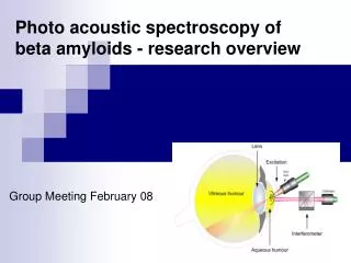
Photothermal Deflection Spectroscopy (PDS) • PDS First used: 1979 • Two Lasers: • Pump • Probe • Temperature Gradient => Gradient in the index of refraction • Useful as a non-destructive spectroscopic method • Can observe microscopic impurities in a crystal • Ex: trace metals in a sapphire crystal
PDS • Probe • Does not disturb sample • Detected • Pump • More powerful • Modulated • Not detected
Deflection (cont.) • Snells law: a sin A = b sin B • (..) = arcsin { (n0)/(n(..)) * sin (pi/2 - )} • = laser angles • = angle of deflection • n0 = index of refraction of sapphire (1.862) • n = index of refraction function caused by PDS
Pump table 700 mW Nd YAG laser Chopper Fiber coupler Fiber Probe table 5 mW He Ne Fiber Telescope 1064 mirror Biconvex lens Sapphire crystal Quad cell Detetector The Experiment: two laser tables
Pump Table 5- axis fiber aligner Polarization Selecting filter chopper Nd YAG
Probe table HeNelaser 1064 mirror Fiber conduit XYZ stage Fiber chuck sample beamtube Aspheric lens holder telescope Photo detector XY stage
Probe Table: laser alignment • Small angle theta in the y direction • Increases interaction length • Beam waists: 80 microns • Nd Yag • Magnified, collimated in telescope • Reflected off mirror • Focused in biconvex lens into sapphire • He - ne • Passes through 1064 mirror • Focused in biconvex lens into sapphire
Data • Initial results were inconclusive with lock- in amplification. • Observed PDS with signal analyzer • Pump power incident: 300 mw • Chopping frequency: 500 Hz • Maximum signal to noise ratio: 27 to 3 • Crystal mapping ongoing