Download
1 / 64
660 likes | 979 Vues
FUNDAMENTALS OF EXTRACTION SYSTEMS. Dr. M.O. Garg Director Indian Institute of Petroleum (Council of Scientific & Industrial Research ) Dehradun. SYMPOSIUM ON SOLVENT EXTRACTION REVISITED FEBRUARY 5 TH , 2010 IIChE (NRC) Auditorium NEW DELHI-INDIA. Outline of Presentation.

E N D
FUNDAMENTALS OF EXTRACTION SYSTEMS Dr. M.O. GargDirectorIndian Institute of Petroleum (Council of Scientific & Industrial Research )Dehradun SYMPOSIUM ON SOLVENT EXTRACTION REVISITED FEBRUARY 5TH, 2010 IIChE (NRC) Auditorium NEW DELHI-INDIA
Outline of Presentation • Introduction • Phase Equilibria and Stage Calculation • Hydrodynamics and Mass Transfer • Design and Scale - up • Concluding Remark
Introduction • Liquid extraction • Separation of components with an insoluble liquid. • Transferring solute distributes itself differently between the two liquid phases resulting in separation. Comparison with Distillation • Distillation • Products comprise essentially substances present in feed • Involves high temp. opns. • Independent unit opn. for separations requirement. • Extraction • New solutions are produced. • Done at suitably low temp. • Normally accompanied by Dist.orEvapn. for recovery.
Introduction(Contd.) Comparison with Distillation • Distillation • May require large no. of theoretical stages. • Plate efficiencies can be as high as 90% • Separates substances which differ in their V.P. • Extraction • Requires typically 3-10 theoretical stages. • Low Plate efficiencies • Major constituents are chemically very different.
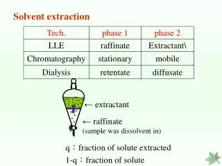
Solvent Extraction • Solvent Extraction process can be broadly divided into two parts • Extraction • Solvent Recovery • While extraction controls yield and quality of products, solvent recovery controls utility consumption
Extraction PROCESS FLOW SHEET Raffi- nate EXTRACT E X T C O L R W C SRC SOL R E G FEED LEAN SOLVENT
Steps for Solvent Extraction Technology Development Selection of Solvent Experimental Data Generation (LLE and Mass Transfer) Generation of Phase Equilibrium Data / Physico -Chemical Properties Prediction / Correlation of Phase Equilibria Mass Transfer Studies Pilot Plant Studies/Scale-Up Process Simulation / Design Extractor Design Diameter Height Scale-up Solvent Recovery Optimization Other Considerations
Solvent Selection Criteria Solvent is the heart of the extraction process and governs the economics of the process. Final choice of solvent will be a compromise between • Corrosiveness • Flammability • Toxicity • Stability • Compatibility with product • Availability and • Cost • Solvent Capacity • Solvent selectivity • Solvent recovery difficulties • Density difference between Dispersed and Continuous Phases • Interfacial tension • Boiling point
Solvent Design • The type of solvent for a particular application is always a matter of discussion • The design of solvent to meet desirable properties may be possible in future with the application of • understanding of intermolecular interactions • group contribution approach for properties estimation • Such developments lead to very cost effective design and offer attractive return on revamp of existing units
NMP Extraction Phase Diagram • Use to optimise: • Temperature • Pressure • S/F • Product yield • Product Properties Extract 0.85 0.87 0.89 0.91 0.93 0.95 0.97 0.99 1.01 1.03 1.05 Sp. Gravity 6 2 1 Raffinate 3 4 5 10 20 30 40 50 60 70 80 90 NMP + Water Wt.%
Phase Equilibria Measurements XiiI=XiiII • Thermodynamic modelling • Sources of data • In-house data generation (IIP) • Literature as published from time to time • DECHEMA • Most of the data reported in terms of concentration than activity coefficient • Scarcity of data - in-house generation of data with relevant feed/solvent Data Compilation Prediction
Phase Equilibria-Measurements • Phase Equilibria with actual system in single stage still • Infinite dilution activity coefficient for simple feeds • It is usually difficult to check thermodynamic consistency of the measured data, hence data generation requires skills
Experimental Data Generation LLE data Batch units ( Mixture Settler) Mass transfer data Extraction studies Packed extractor (34 mm dia, 1.5 m height) Solvent Recovery (Distillation) studies 1” diaOldershaw columns Up to 50 actual stages
Phase Equilibria-Prediction Feed/product fluids are complex mixtures, need to be characterized • To predict phase equilibria • To understand physico-chemical behaviour
Feed Characterization • Defined Components (CO2, H2S, C1 to C6 ) • Well Defined using gas chromatography analysis • C7+ Characterisation • Pseudo component approach • Continuous thermodynamics approach • Structured Oriented Lumping approach • Pseudo component approach is well established and normally employed • Continuous approach have been used for solvent deasphalting, but still under development • Not much information available about application of SOL in solvent extraction
Feed Characterization • Solvent extraction studies such as kerosene extraction, lube extraction, solvent deasphalting requires detailed feed analysis such as GC-MS, NMR, Liquid Chromatography apart from physical characteristics. • All of these facilities available at IIP • Identification of pseudo components is a specialised job and have been carried out for number of feedstocks
Phase Equilibria-Prediction • Activity Coefficients Model • NRTL, UNIQUAC etc • Group Contribution Approach (UNIFAC) • Model parameters normally binary and are fitted as function of temperature • Non uniqueness of parameters - same set of data can be represented with different set of parameters • Successfully applied for sulfolane extraction (NRTL), lube extraction (UNIFAC).
Phase Equilibrium Correlation / Prediction • Selection of Thermodynamic Model • For lighter fractions i.e. upto Naphtha Range • NRTL/UNIQUAC • For heavier fractions eg. Kerosene, Diesel, etc. • UNIFAC • Model Parameters • From Experimental Data (Data Reconciliation necessary ) • From Literature (DECHEMA)
DECISION MAKING CHART LLE NRTL - UNIQUAC Kij Y P< 10 bar Wilson - NRTL - UNIQUAC LLE Kij N UNIFAC LLE Non el. UNIFAC Kij Y Polar RS Pol - MHV2 - SAFT P> 10 bar Kij N PSRK - RKSMHV2 Electrolyte Elect- NRTL Real Non Polar RK - PR - SRK - LK > 1 atm Chao S - Greyson Pseudo Vacuum BK10 - Ideal
Simulation of Solvent Extraction Process • Simulation Studies • Inhouseprogrammes • Commercial Softwares • ASPEN/ PRO II • Validation of Simulations • Experimental Data • Industrial Data
Simulation of Solvent Extraction Process • Process Specifications • Feed Rate • Product Quality / Quantity • Operating Temperature / Pressure • Simulation Studies to determine • S/F Ratio • Product Quality / Quantity • Material Balance • Utility Requirements, Optimization
Design of Extractor • Type of extractor • Choice of dispersed phase • Diameter • Height
Extraction Equipment 25 different types of extractors are in commercial use. Reasons for its diversity • Extraction is a widely used separation process and the equipment must suit the individual characteristics of a process. • In-house development by Licensors
Contacting of Phases • Without external energy input • Use of gravitational force • With external energy input • Mechanical energy • Rotation/Pulsation/Reciprocation • Agitation creates & maintains dispersion
Contacting of Phases(contd.) • Stagewise Contacting • Discrete Units/Stages • In each Unit/Stage phase are • Contacted - Mixed - Separated & sent to next unit • Equilibrium or approach to it achieved in each of these stages
Contacting of Phases(Contd.) • Continuous Contacting • Phases separated only at ends • Mass transfer along the full length • Equilibrium not reached at any point
Extractors (Contd.) Extractor Spray Column • Features • Generally 1-2 theo. Stages possible • Low capital • Operating & maintenance cost • Massive continuous phase entrainment • Simple in construction • Application • Food • Chemical Industries
Extractors (Contd.) Sieve Tray • Features • Higher residence time • Less flexibility of opn. • Preferable for dirty services • Low liquid thru’put • Corrosion & foaming services • Application • Petrochemical Industries
P* } h { Z d P P 2 1 Sieve Tray Extractor
Extractors (Contd.) Packed Column • Features • Less no. of theo. Stages • Increased thru’put and mass transfer area • Reduced backmixing • Improved turn-down ratio • Reduced pressure drop • Application • Petrochemical & Chemical Industries
Packed Column • Packed column provide a good future prospects in existing and new applications • Structured packing may find more applications in future • Distributor designs are critical • Rigorous mathematical modelling like CFD can improve design of distributors and other internals
Packed Column with Structured Packings • Structured packings although expensive being used in various services • Offer larger throughput and avoid maldistribution of dispersed phase • Being successfully used in solvent deasphalting application • Attractive in part of the column to enhance coalescence • Clogging due to degraded and corrosive products is possible
Extractors : Mixer Settler • Features • High Stage Efficiency • Wide Solvent Ratios • High Capacity • Good Flexibility • Scale up • Handles Viscous Substances • Application • Petrochemical, Nuclear, Fertilizer & Metallurgical Industries
Extractors RDC • Features • Reasonable Capacity & HETS • Many stages possible • Reasonable Construction Cost • Low Operating & Maintenance Costs • Application • Petrochemical • Metallurgical • Pharma & Fertilizer
Extractors Light liquid Out Heavy liquid In Light liquid In Heavy liquid out baffle tower
Mechanically Agitated Columns • Do not provide consistent performance over wide range of operation • Most of the RDC being used today are NOT operated with Rotor • Due to their high stage efficiencies, these columns are preferred for laboratory studies
Extractors (Contd.) Centrifugal Extractor • Features • Short contacting time • LTD. space required • Handles easily emulsified materials and system with low density difference • Application • Pharmaceutical • Nuclear • Petrochemical
Extractors in Petroleum Industry • Extractor type Applications • RDC BTX, Lubes • Sieve Plate BTX • Packed Column Lubes • Mixer Settler BTX • Baffle Column Deasphalting
Dispersion For effective contacting of phases one phase is dispersed in another Dispersed Phase Continuous Phase
Continuous Phase VS Dispersed Phase Solvent- continuous Feed- continuous
Criteria for Dispersion • Which phase to Disperse ?Disperse the phase • With higher volumetric rate • To increase interfacial area • Which does not preferentially wet the Plate/Packings • To avoid coalescence • With more Viscosity • More Costly • Holdups are generally ~10% • Capital investment less • More Flammable • Solvent Phase • Less coalescence
Column DiameterDepends upon variables • Phase flow(v) ratio • Droplet mean diameter • Physical properties, c, d, c, d and • Agitation energy, if applicable • Geometry of column internals
Column Height Depends on factors in addition considered for Diameter • Equilibrium relationship • Drop size distribution • Hold up and throughput • Mass transfer coefficients • Backmixing • Radial Mixing • Drop breaking & coalescence
Column Diameter Slip Velocity Concept Vslip=Vd/¤+Vc/(1-¤) where, ¤ is hold up Slip velocity correlations Vslip=Vo(1-¤) Vslip= Vo (1-¤)n Vslip= Vo (1-¤)exp(a¤) where, Vo is characteristic velocity(slip velocity extrapolated to ¤=0 )
Column Diameter Flooding ( maximum attainable holdup) dVd/d¤ = 0 and dVc/d¤ = 0